
Alternator/Regulator Operation Test (page 3 of 3)
- Make
- Rover
- Model
- 600 Rover 600 Repair Manual - Volumes 1 and 2 - 2nd Edition
- Section
- Repairs
ElectricalAlternator/Regulator Operation Test · page 3 of 3
- Remove the power steering pump, see STEERING.
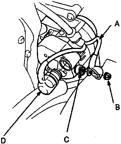
A B terminal wire (WHT/RED)
B Terminal nut
C B terminal
D 4 – P connector
- Disconnect the 4 – P connector from the alternator.
- Remove the terminal nut and the B terminal (WHT/RED) wire from the B terminal.
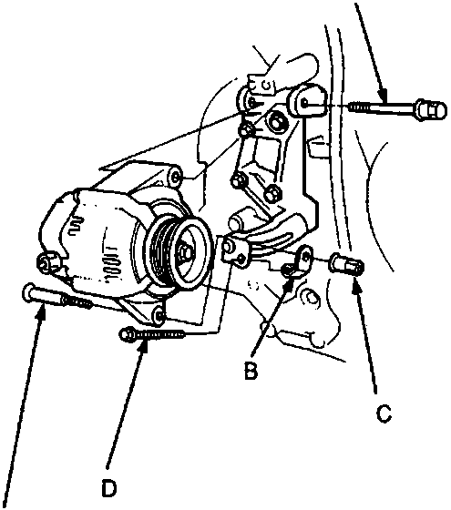
A Through bolt
B Adjusting nut
C Adjustment locknut
D Adjusting bolt
E Adjustment bolt
- Loosen the through bolt, then loosen the adjustment locknut and the adjusting bolt.
- Remove the belt from the alternator.
- Remove the adjustment bolt and nut.
- Remove the through bolt, then remove the alternator.
- Install in the reverse order of removal.
Note:
- After installing the alternator, adjust the alternator belt tension and the power steering pump belt tension, see STEERING.
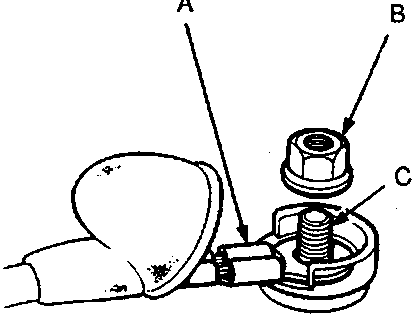
A Crimped side of the ring terminal
B Nut
C Terminal
Parts & tools for this job For Rover 600
- TOOLBattery testerSearch: car battery tester
- TOOLDigital multimeterSearch: automotive digital multimeter
- TOOLBattery terminal cleanerSearch: battery terminal cleaner
Links open Amazon search results in a new tab. As an Amazon Associate I earn from qualifying purchases.