
Removal
- Make
- Rover
- Model
- 600 Rover 600 Repair Manual - Volumes 1 and 2 - 2nd Edition
- Section
- Repairs › Removal
ElectricalRemoval
Removal
CAUTION: Be careful not to damage the consoles.
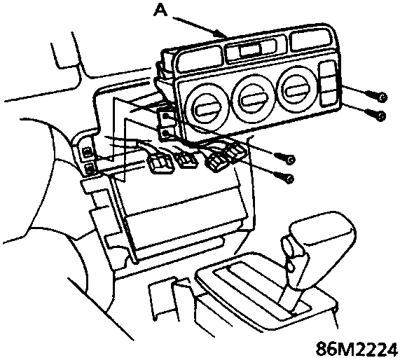
- A Heater control panel assembly
- Remove the rear console, see BODY.
- Remove the front console, see BODY.
- Remove the heater control panel assembly, see HEATING & VENTILATION.
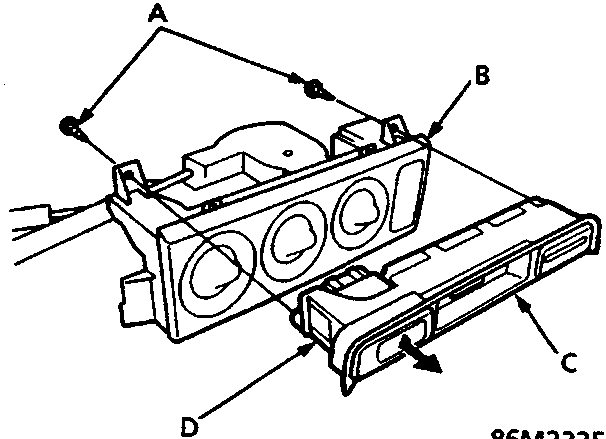
- A Screws
- B Heater control panel
- C Clock
- D Hazard warning switch
Terminals
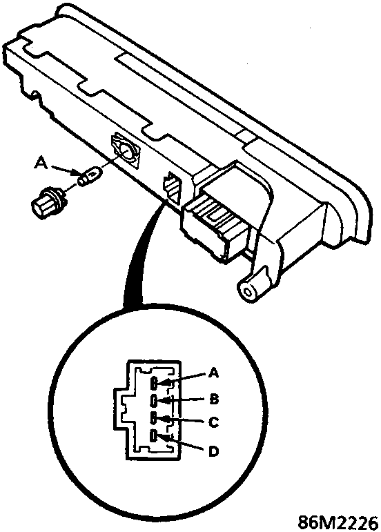
- A Bulb (1.2W)
| Terminal | Wire | Connects to |
|---|---|---|
| A | WHT/YEL | Constant power (time memory) |
| B | YEL | IG¹ (main clock power supply) |
| C | RED/BLK | Lights – on signal |
| D | BLK | Earth |
- Separate the clock from the heater control panel by removing the two screws.
- If necessary, pry the hazard warning switch out from the clock.
- Install in the reverse order of removal.
Parts & tools for this job For Rover 600
- TOOLDigital multimeterSearch: automotive digital multimeter
- PARTAssorted fuse kitSearch: car fuse assortment kit
- TOOLWire crimper and connector kitSearch: wire crimper connector kit
Links open Amazon search results in a new tab. As an Amazon Associate I earn from qualifying purchases.