
Original page
- Make
- Rover
- Model
- 600 Rover 600 Repair Manual - Volumes 1 and 2 - 2nd Edition
- Section
- Repairs › Original page
ElectricalOriginal page
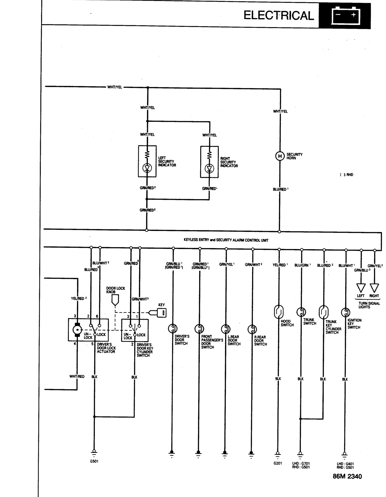
- LEFT SECURITY INDICATOR
- RIGHT SECURITY INDICATOR
- SECURITY HORN
- DRIVER'S DOOR LOCK ACTUATOR
- DRIVER'S DOOR KEY CYLINDER SWITCH
- DOOR LOCK KNOB
- DRIVER'S DOOR SWITCH
- FRONT PASSENGER'S DOOR SWITCH
- L.REAR DOOR SWITCH
- R.REAR DOOR SWITCH
- HOOD SWITCH
- TRUNK SWITCH
- TRUNK KEY CYLINDER SWITCH
- IGNITION KEY SWITCH
- TURN SIGNAL LIGHTS
Original page
Parts & tools for this job For Rover 600
- TOOLDigital multimeterSearch: automotive digital multimeter
- PARTAssorted fuse kitSearch: car fuse assortment kit
- TOOLWire crimper and connector kitSearch: wire crimper connector kit
Links open Amazon search results in a new tab. As an Amazon Associate I earn from qualifying purchases.