
Test
- Make
- Rover
- Model
- 600 Rover 600 Repair Manual - Volumes 1 and 2 - 2nd Edition
- Section
- Repairs › Test
ElectricalTest
Test
- Remove the console, then disconnect the 12-P and 2-P connectors from the switch.
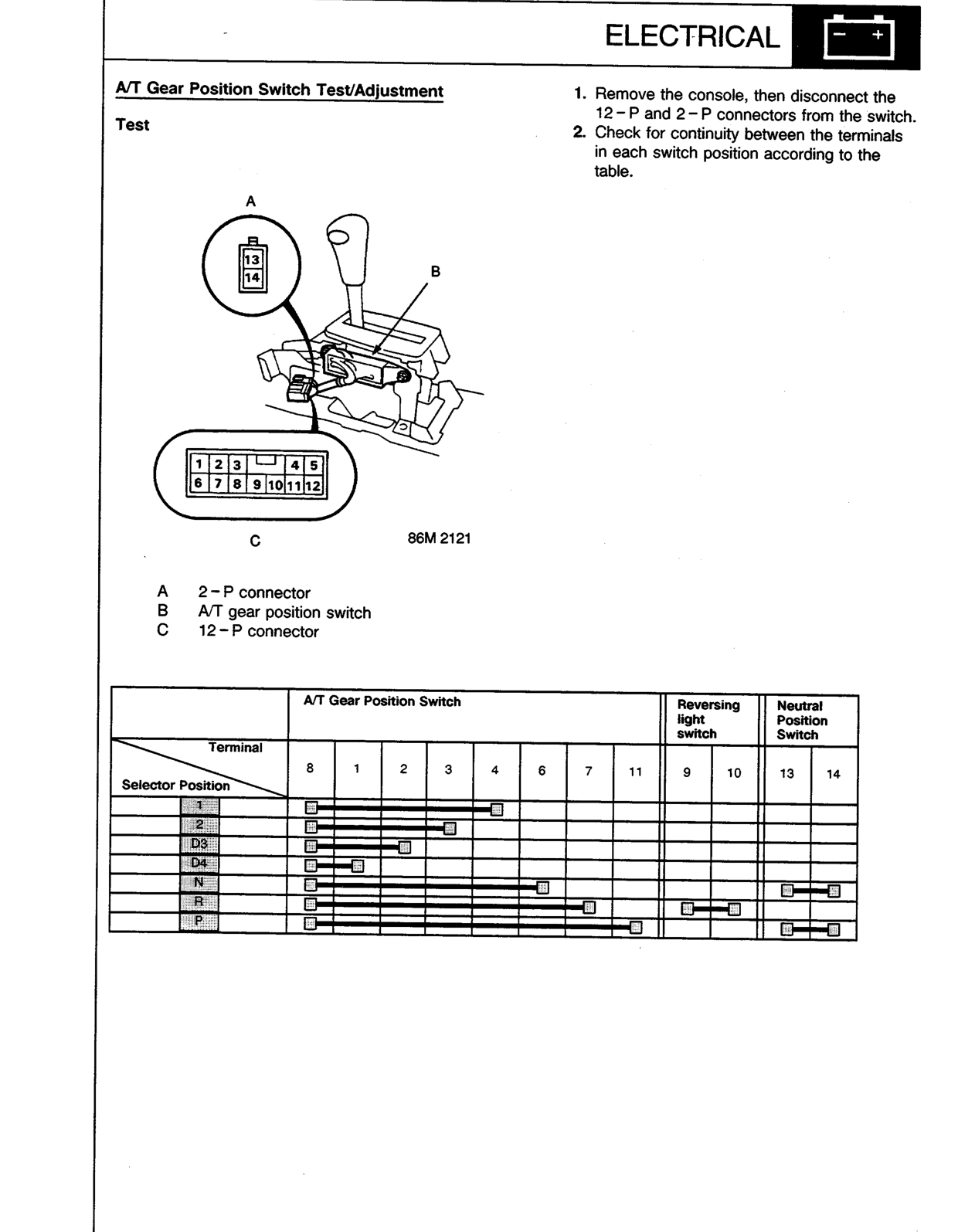
- Check for continuity between the terminals in each switch position according to the table.
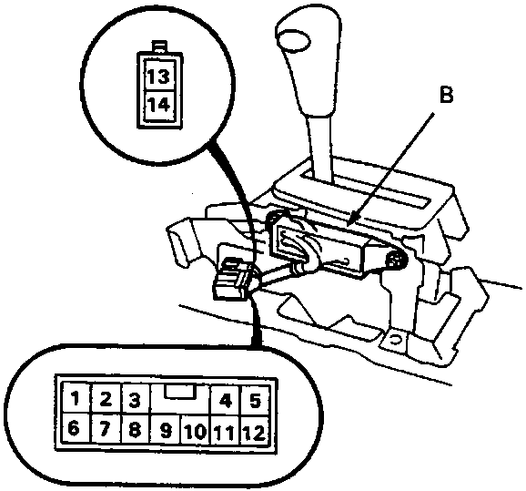
86M 2121
- A 2-P connector
- B A/T gear position switch
- C 12-P connector
| Selector Position | A/T Gear Position Switch | Reversing light switch | Neutral Position Switch | |||||||||
|---|---|---|---|---|---|---|---|---|---|---|---|---|
| Terminal 8 | 1 | 2 | 3 | 4 | 6 | 7 | 11 | 9 | 10 | 13 | 14 | |
| 1 | ● | ● | ● | ● | ● | |||||||
| 2 | ● | ● | ● | ● | ||||||||
| D3 | ● | ● | ● | |||||||||
| D4 | ● | ● | ||||||||||
| N | ● | ● | ● | ● | ● | ● | ● | |||||
| R | ● | ● | ● | ● | ● | ● | ● | ● | ||||
| P | ● | ● | ● | ● | ● | ● | ● | ● | ● | |||
Original page
Parts & tools for this job For Rover 600
- TOOLDigital multimeterSearch: automotive digital multimeter
- PARTAssorted fuse kitSearch: car fuse assortment kit
- TOOLWire crimper and connector kitSearch: wire crimper connector kit
Links open Amazon search results in a new tab. As an Amazon Associate I earn from qualifying purchases.