
Control Unit Input Test
- Make
- Rover
- Model
- 600 Rover 600 Repair Manual - Volumes 1 and 2 - 2nd Edition
- Section
- Repairs › Control Unit Input Test
ElectricalControl Unit Input Test
Control Unit Input Test
WARNING: Observe SRS system precautions, see SRS PRECAUTIONS.
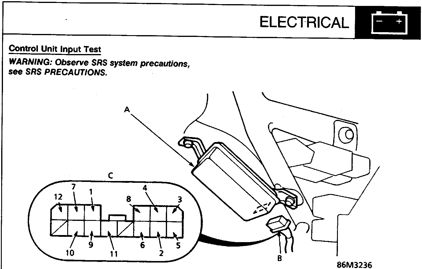
A Cruise control unit
B Multiplug – 14 pin
C Multiplug view from wire side showing test numbers.
- Remove dashboard lower cover.
- Disconnect 14 – P connector from control unit.
- Inspect connector and socket terminals, ensure they are all making good contact.
- If terminals are bent, loose or corroded, repair them as necessary and recheck system.
If terminals look OK, make the input tests at the connector as shown in the following table:
- – If any test indicates a problem, find and correct the cause, then recheck the system.
- – If all the input tests prove OK, replace the control unit.
Control Unit Replacement
WARNING: Observe SRS system precautions, see SRS PRECAUTIONS.
- Remove dashboard lower cover.
- Remove 2 bolts securing control unit to dash rail.
- Disconnect 14 – P connector from control unit.
- Remove cruise control unit.
- Reverse removal procedure to install.
Parts & tools for this job For Rover 600
- TOOLDigital multimeterSearch: automotive digital multimeter
- PARTAssorted fuse kitSearch: car fuse assortment kit
- TOOLWire crimper and connector kitSearch: wire crimper connector kit
Links open Amazon search results in a new tab. As an Amazon Associate I earn from qualifying purchases.