
Engine oil pressure warning system
- Make
- Rover
- Model
- 600 Rover 600 Repair Manual - Volumes 1 and 2 - 2nd Edition
- Section
- Repairs › Engine oil pressure warning system
ElectricalEngine oil pressure warning system
ENGINE OIL PRESSURE WARNING SYSTEM
Pressure Switch Test
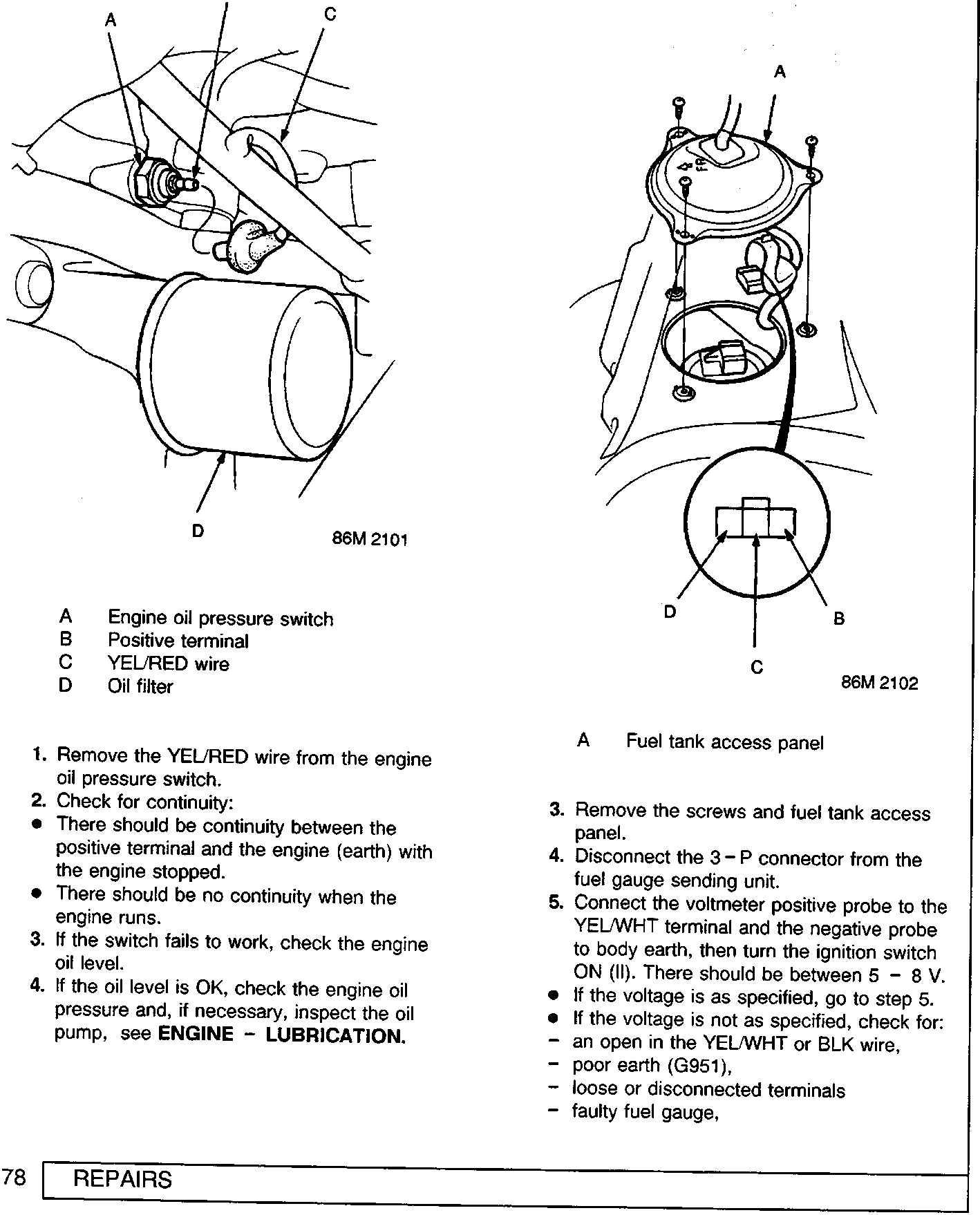
- Engine oil pressure switch
- Positive terminal
- YEL/RED wire
- Oil filter
- Remove the YEL/RED wire from the engine oil pressure switch.
- Check for continuity:
- There should be continuity between the positive terminal and the engine (earth) with the engine stopped.
- There should be no continuity when the engine runs.
- If the switch fails to work, check the engine oil level.
- If the oil level is OK, check the engine oil pressure and, if necessary, inspect the oil pump, see ENGINE - LUBRICATION.
FUEL GAUGE
Gauge Test
Note: Refer to fuel system circuit diagram
- Check the No. 8 (10 A) fuse in the passenger compartment fuse/relay box before testing.
- Open the boot and remove the floor trim panel, then turn the right rear seat forward.
- A Fuel tank access panel
- Remove the screws and fuel tank access panel.
- Disconnect the 3 – P connector from the fuel gauge sending unit.
- Connect the voltmeter positive probe to the YEL/WHT terminal and the negative probe to body earth, then turn the ignition switch ON (II). There should be between 5 – 8 V.
- If the voltage is as specified, go to step 5.
- If the voltage is not as specified, check for:
- an open in the YEL/WHT or BLK wire,
- poor earth (G951),
- loose or disconnected terminals
- faulty fuel gauge,
Parts & tools for this job For Rover 600
- PARTEngine gasket setSearch: Rover 600 engine gasket set
- TOOLTorque wrenchSearch: 3/8 inch torque wrench
- TOOLFeeler gauge setSearch: feeler gauge set
Links open Amazon search results in a new tab. As an Amazon Associate I earn from qualifying purchases.