
Entry Light Timer System
- Make
- Rover
- Model
- 600 Rover 600 Repair Manual - Volumes 1 and 2 - 2nd Edition
- Section
- Repairs › Entry Light Timer System
ElectricalEntry Light Timer System
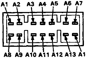
A View from terminal side
B View from wire side
Entry Light Timer System
| No. | Terminal | Test condition | Test: Desired result | Possible cause if result is not obtained |
|---|---|---|---|---|
| 1 | A8 | Under all conditions | Check for continuity to earth: There should be continuity. | ● Poor earth (G401) ● An open in the wire |
| 2 | A12 | Under all conditions | Check for voltage to earth: There should be battery voltage. | ● Blown No. 29 (15A) fuse in the engine compartment fuse/relay box ● An open in the wire |
| 3 | WHT/BLK | Under all conditions | Connect to earth; Ignition key light should come on. | ● Blown bulb ● An open in the wire |
| 4 | BLK/WHT. | Interior light switch in "MIDDLE" position | Connect to earth: Interior lights should come on. | ● Blown No. 29 (15A) fuse in the engine compartment fuse/relay box ● Faulty front ceiling light switch ● Blown bulb ● An open in the wire |
| 5 | BLK/WHT. | Driver's door open | Check for voltage to earth: There should be 1V or less. Note: Use a digital multimeter. | ● Faulty driver's door switch ● An open in the wire. |
Daytime Running Lights System (KS)
| No. | Terminal | Test condition | Test: Desired result | Possible cause if result is not obtained |
|---|---|---|---|---|
| 1 | A8 | Under all conditions | Check for continuity to earth: There should be continuity. | ● Poor earth (G401) ● An open in the wire |
| 2 | RED/GRN | Under all conditions | Check for voltage to earth: There should be battery voltage. | ● Blown No. 19 (30A) fuse in the engine compartment fuse/relay box ● An open in the wire |
| 3 | A13 | Headlights switch ON | Check for voltage to earth: There should be battery voltage. | ● Blown No. 19 (30A) fuse in the engine compartment fuse/relay box ● Faulty combination light switch ● An open in the wire |
| 4 | RED/BLU | Combination light switch ON (second position) | Check for voltage to earth: There should be battery voltage | ● Faulty combination light switch ● Faulty headlight relay ● An open in the wire |
| 5 | BLU/RED | Passing switch ON | Check for voltage to earth: There should be battery voltage | ● Faulty combination light switch ● Faulty headlight relay ● Faulty dip relay ● An open in the wire. |
| 6 | YEL/RED | Ignition switch ON | Check for voltage to earth: There should be battery voltage. | ● Blown No. 10 (7.5A) fuse in the passenger compartment fuse/relay box ● An open in the wire |
| 7 | A14 | Connect the RED/GRN terminal to the A14 | Front position lights, tail lights and number plate lights should come on. | ● Blown bulbs ● An open in the wire |
| 8 | BLU/WHT | Dip switch HI | Check for continuity to earth: There should be continuity. | ● faulty combination light switch ● Poor earth (G401) ● An open in the wire |
Parts & tools for this job For Rover 600
- TOOLDigital multimeterSearch: automotive digital multimeter
- PARTAssorted fuse kitSearch: car fuse assortment kit
- TOOLWire crimper and connector kitSearch: wire crimper connector kit
Links open Amazon search results in a new tab. As an Amazon Associate I earn from qualifying purchases.