
Replacement
- Make
- Rover
- Model
- 600 Rover 600 Repair Manual - Volumes 1 and 2 - 2nd Edition
- Section
- Repairs › Replacement
ElectricalReplacement
Replacement
CAUTION:
- All SRS electrical wiring harnesses are covered with yellow outer insulation.
- Replace the entire affected SRS harness assembly if it has an open circuit or damaged wiring.
- Before disconnecting the SRS wiring harness, turn the ignition switch off, disconnect the negative and positive battery cables, and wait at least three minutes, see SUPPLEMENTARY RESTRAINT SYSTEM.
- Remove the screws and dashboard lower cover, then disconnect the connector(s) from the switch(es).
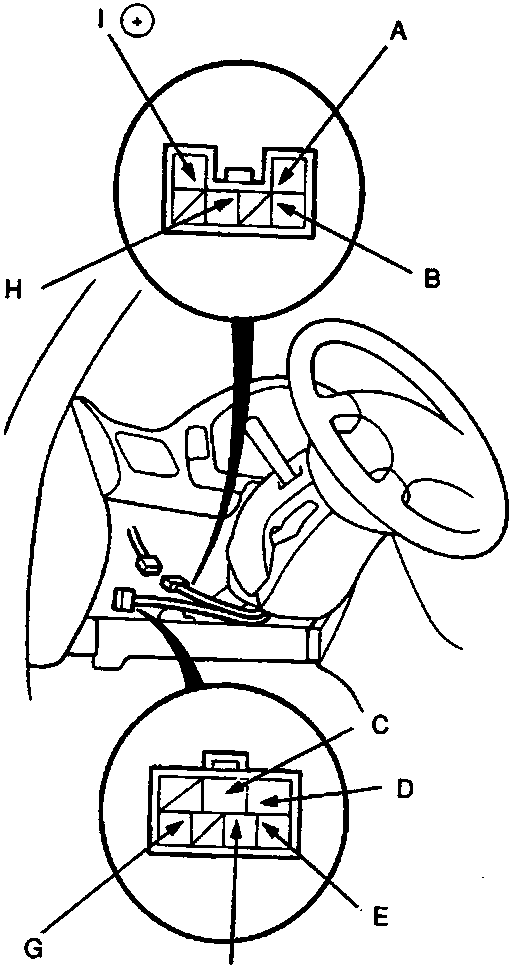
- A WHT/BLK (key light)
- B BLU/WHT (key)
- C IG2
- D WHT (bat)
- E BLK/WHT (ST)
- F BLK/YEL (IG1)
- G WHT/BLK (ACC)
- H BLK (Earth)
86M 1987
- Remove the steering column covers.
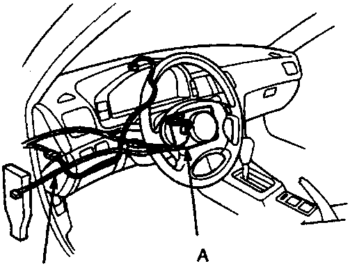
- A Column upper cover
- B Column lower cover
86M 1988
Parts & tools for this job For Rover 600
- TOOLDigital multimeterSearch: automotive digital multimeter
- PARTAssorted fuse kitSearch: car fuse assortment kit
- TOOLWire crimper and connector kitSearch: wire crimper connector kit
Links open Amazon search results in a new tab. As an Amazon Associate I earn from qualifying purchases.