
Component Location
- Make
- Rover
- Model
- 600 Rover 600 Repair Manual - Volumes 1 and 2 - 2nd Edition
- Section
- Repairs › Component Location
ElectricalComponent Location · page 1 of 3
Component Location
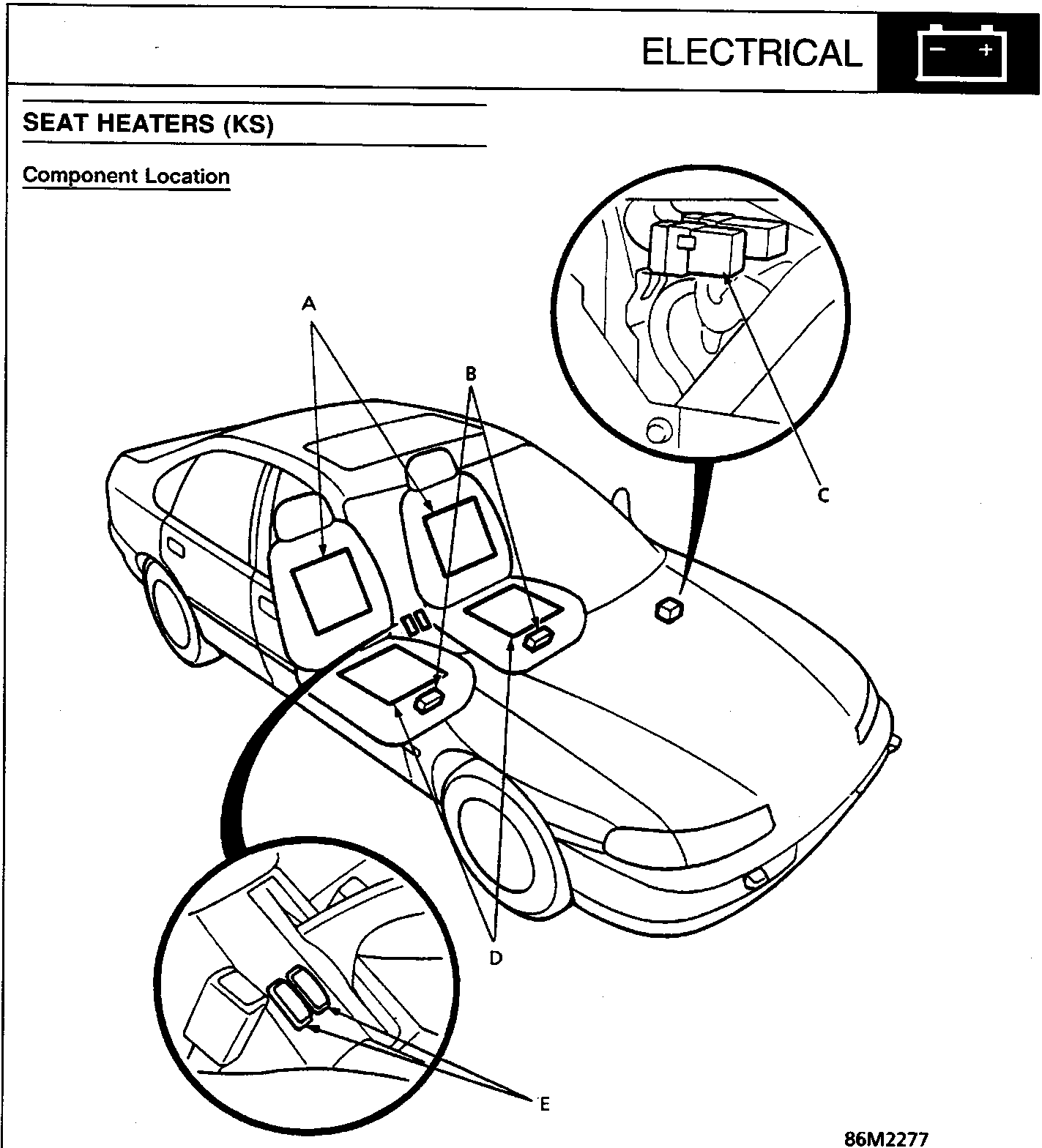
A Seat back heaters
B Seat heater relays
C Seat heater main relay
D Seat cushion heaters
E Seat heater switches
Description
Two heaters are provided in each front seat; one in the seat cushion and another in the seat back. In normal use, temperature is automatically controlled by the thermostat [OFF above 40.C (104.F)] built into each seat cushion heater. Breaker 1 [OFF above 50.C (122.F)] and breaker 2 [OFF above 70.C (158.F)] cut off the circuit to prevent abnormal temperature rise.
Parts & tools for this job For Rover 600
- TOOLDigital multimeterSearch: automotive digital multimeter
- PARTAssorted fuse kitSearch: car fuse assortment kit
- TOOLWire crimper and connector kitSearch: wire crimper connector kit
Links open Amazon search results in a new tab. As an Amazon Associate I earn from qualifying purchases.