
SRS Type II
- Make
- Rover
- Model
- 600 Rover 600 Repair Manual - Volumes 1 and 2 - 2nd Edition
- Section
- Repairs › SRS Type II
ElectricalSRS Type II · page 1 of 2
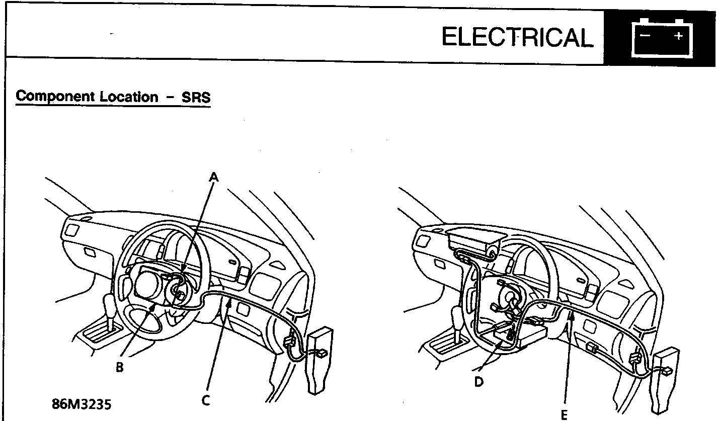
86M3235
SRS Type II
- A SRS unit sub – harness
- B SRS unit (built – in sensors)
- C SRS main harness (covered with YELLOW insulation)
SRS Type III
- D SRS unit (built – in sensors)
- E SRS main harness (covered with YELLOW insulation)
SRS PRECAUTIONS
- All SRS wire harnesses are covered with YELLOW insulation.
- Replace the entire SRS harness if it has an open circuit or damaged wiring.
Before disconnecting any part of the SRS circuit, turn the ignition switch off, disconnect the negative and then the positive battery cables, then wait at least 3 minutes.
- Whenever the ignition is switched ON (II) or has been turned off for less than 3 minutes, be careful not to accidentally bump the SRS unit; the airbags could deploy and cause damage or injuries.
- Before disconnecting any part of an SRS wiring harness, short the wires in the RED connector.
- Refer to additional precautions in the SRS section.
Parts & tools for this job For Rover 600
- TOOLOBD2 scanner with SRSSearch: OBD2 scanner ABS SRS
- TOOLTrim removal tool kitSearch: trim removal tool kit
Links open Amazon search results in a new tab. As an Amazon Associate I earn from qualifying purchases.