
Combination light switch
- Make
- Rover
- Model
- 600 Rover 600 Repair Manual - Volumes 1 and 2 - 2nd Edition
- Section
- Repairs › Combination light switch
ElectricalCombination light switch
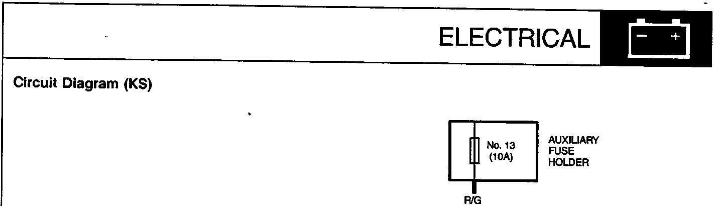
No. 13 (10A) AUXILIARY FUSE HOLDER
R/G
COMBINATION LIGHT SWITCH
No. 10 (7.5A) FUSE
Y/R
R/G
R/U
U/R
U/W
DAYTIME RUNNING LIGHT CONTROL CIRCUIT (In the integrated control unit)
R/B
R/B
R/Y
R/B
R/B
R/B
R/B
R/B
B
G203
LEFT FRONT PARKING LIGHT (5W)
G301
B
RIGHT FRONT PARKING LIGHT (5W)
G201
B
LEFT TAILLIGHT (5W)
G501
B
RIGHT TAILLIGHT (5W)
G452
B
LICENCE PLATE LIGHTS (5W x 2)
G501
B
DASH LIGHTS DASH LIGHTS BRIGHTNESS CONTROLLER A/T GEAR POSITION CONSOLE LIGHT
Parts & tools for this job For Rover 600
- TOOLOBD2 scannerSearch: OBD2 scanner
- TOOLDigital multimeterSearch: automotive digital multimeter
- TOOLBack-probe test leadsSearch: back probe test leads
Links open Amazon search results in a new tab. As an Amazon Associate I earn from qualifying purchases.