
86M 2403
- Make
- Rover
- Model
- 600 Rover 600 Repair Manual - Volumes 1 and 2 - 2nd Edition
- Section
- Repairs › 86M 2403
Electrical86M 2403
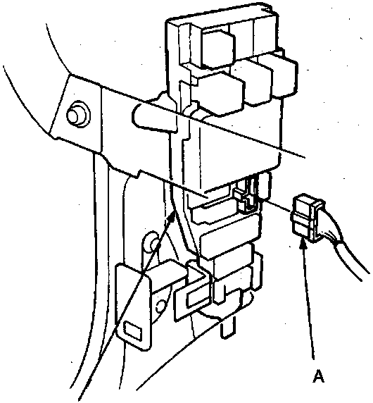
5. Remove the switch cover and switch by removing the bolts.
6. Install in the reverse order of removal.
86M 2403
- Disconnect the 7 – P connector from the passenger compartment fuse/relay box.
- Turn the ignition switch to "0".
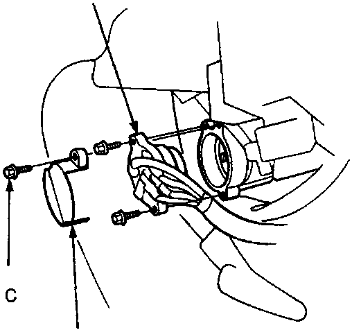
86M 2404
| A | Ignition switch |
| B | Switch cover |
| C | Bolt |
Parts & tools for this job For Rover 600
- TOOLDigital multimeterSearch: automotive digital multimeter
- PARTAssorted fuse kitSearch: car fuse assortment kit
- TOOLWire crimper and connector kitSearch: wire crimper connector kit
Links open Amazon search results in a new tab. As an Amazon Associate I earn from qualifying purchases.