
Actuator cable adjustment
- Make
- Rover
- Model
- 600 Rover 600 Repair Manual - Volumes 1 and 2 - 2nd Edition
- Section
- Repairs › Actuator cable adjustment
ElectricalActuator cable adjustment · page 1 of 3
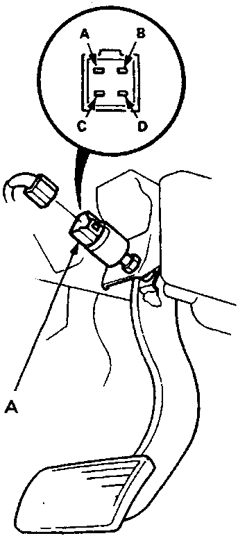
86M3254
A Brake switch
- Disconnect 4 – P connector from brake pedal switch.
- Check for continuity between terminals according to table.
- If necessary, adjust pedal height or replace switch.
| Terminal | A | B | C | D |
|---|---|---|---|---|
| Brake Pedal | ||||
| PRESSED | ■—■ | ■—■ | ||
| RELEASED | ■—■ | ■—■—■—■ | ■—■—■—■ | ■—■ |
Actuator cable adjustment
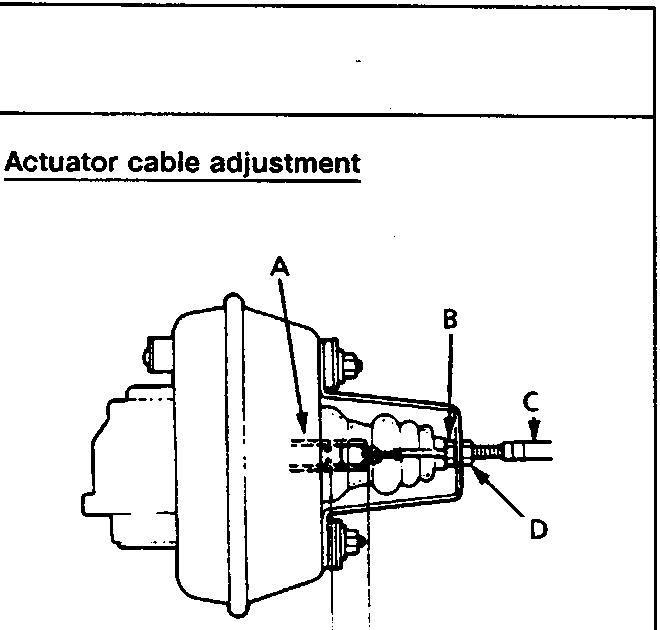
86M3255
| A | Actuator rod |
| B | Adjusting nut |
| C | Actuator cable |
| D | Locknut |
| E | Locknut free play |
- Check that actuator cable operates smoothly with no binding or sticking.
- Start engine and allow to warm up, cooling fan comes and switches off.
- Measure amount of actuator rod movement until cable pulls on accelerator lever, engine speed starts to increase.
Free play = 11 ± 1.5 mm
Adjustment
- Loosen locknut and turn adjusting nut as required.
Note: If necessary, check throttle cable free play, then recheck actuator rod free play.
- Tighten locknut and recheck free play.
Parts & tools for this job For Rover 600
- TOOLDigital multimeterSearch: automotive digital multimeter
- PARTAssorted fuse kitSearch: car fuse assortment kit
- TOOLWire crimper and connector kitSearch: wire crimper connector kit
Links open Amazon search results in a new tab. As an Amazon Associate I earn from qualifying purchases.