
86M 2082
- Make
- Rover
- Model
- 600 Rover 600 Repair Manual - Volumes 1 and 2 - 2nd Edition
- Section
- Repairs › 86M 2082
Electrical86M 2082
Note: Bleed air from the cooling system after installing the engine coolant temperature (ECT) switch.
- Remove the engine coolant temperature (ECT) switch A from the thermostat housing and the engine coolant temperature (ECT) switch B from the water outlet housing.
86M 2082
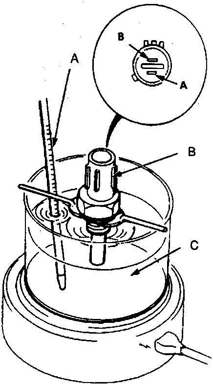
- A Thermometer
- B ECT switch
- C Water or oil
- Suspend each ECT switch in a container of water or engine oil as shown.
Note: The illustration shows ECT switch A.
- Heat the water or engine oil and check coolant temperature with a thermometer.
| Operation | Temperature | Terminal | ||
|---|---|---|---|---|
| A | B | |||
| Switch A | ON | 90 – 96 °C | ● | |
| OFF | 2 – 7 °C lower than switch on temperature. | |||
| SWITCH B | ON | 103 – 109 °C | ● | |
| OFF | 4 – 9 °C lower than switch on temperature. | |||
- Check each ECT switch for continuity between the A and B terminals according to the table.
Parts & tools for this job For Rover 600
- TOOLDigital multimeterSearch: automotive digital multimeter
- PARTAssorted fuse kitSearch: car fuse assortment kit
- TOOLWire crimper and connector kitSearch: wire crimper connector kit
Links open Amazon search results in a new tab. As an Amazon Associate I earn from qualifying purchases.