
Driver's Window Motor Test
- Make
- Rover
- Model
- 600 Rover 600 Repair Manual - Volumes 1 and 2 - 2nd Edition
- Section
- Repairs › Driver's Window Motor Test
ElectricalDriver's Window Motor Test · page 1 of 3
Driver's Window Motor Test
Motor Test
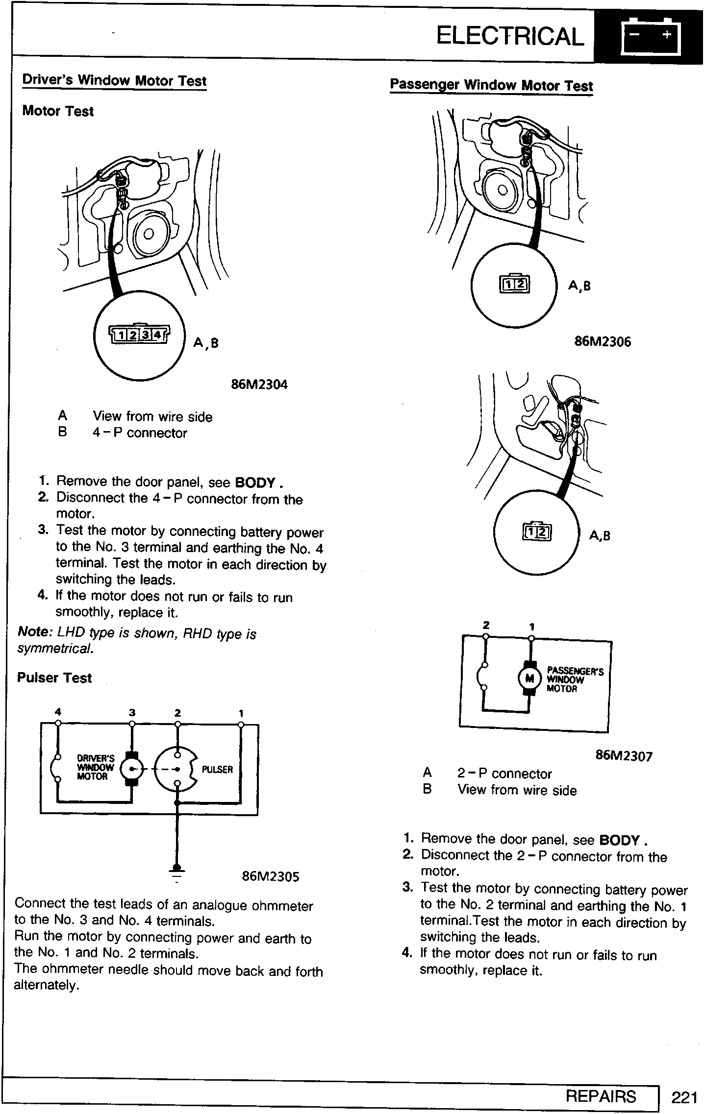
A
B
View from wire side
4 – P connector
- Remove the door panel, see BODY.
- Disconnect the 4 – P connector from the motor.
- Test the motor by connecting battery power to the No. 3 terminal and earthing the No. 4 terminal. Test the motor in each direction by switching the leads.
- If the motor does not run or fails to run smoothly, replace it.
Note: LHD type is shown, RHD type is symmetrical.
Pulser Test
Connect the test leads of an analogue ohmmeter to the No. 3 and No. 4 terminals.
Run the motor by connecting power and earth to the No. 1 and No. 2 terminals.
The ohmmeter needle should move back and forth alternately.
Passenger Window Motor Test
A
B
2 – P connector
View from wire side
- Remove the door panel, see BODY.
- Disconnect the 2 – P connector from the motor.
- Test the motor by connecting battery power to the No. 2 terminal and earthing the No. 1 terminal.Test the motor in each direction by switching the leads.
- If the motor does not run or fails to run smoothly, replace it.
Parts & tools for this job For Rover 600
- TOOLTrim removal tool kitSearch: trim removal tool kit
- PARTTouch-up paintSearch: Rover touch up paint
- PARTPanel clip assortmentSearch: Rover panel clips assortment
Links open Amazon search results in a new tab. As an Amazon Associate I earn from qualifying purchases.