
Original page
- Make
- Rover
- Model
- 600 Rover 600 Repair Manual - Volumes 1 and 2 - 2nd Edition
- Section
- Repairs › Original page
ElectricalOriginal page · page 1 of 5
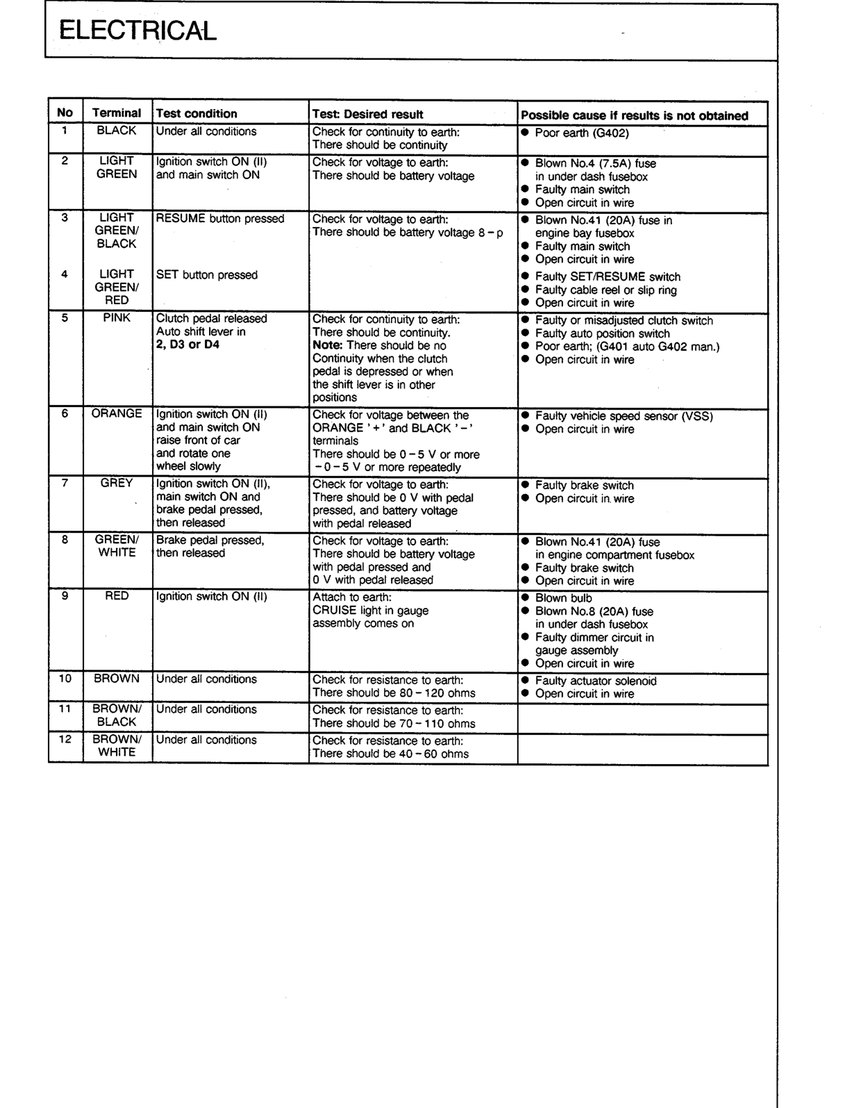
| No | Terminal | Test condition | Test: Desired result | Possible cause if results is not obtained |
|---|---|---|---|---|
| BLACK | Under all conditions | Check for continuity to earth: There should be continuity |
● Poor earth (G402) | |
| 2 | LIGHT GREEN | Ignition switch ON (II) and main switch ON |
Check for voltage to earth: There should be battery voltage |
● Blown No.4 (7.5A) fuse in under dash fusebox ● Faulty main switch ● Open circuit in wire |
| 3 | LIGHT GREEN/BLACK | RESUME button pressed | Check for voltage to earth: There should be battery voltage 8 – p |
● Blown No.41 (20A) fuse in engine bay fusebox ● Faulty main switch ● Open circuit in wire |
| 4 | LIGHT GREEN/RED | SET button pressed | ● Faulty SET/RESUME switch ● Faulty cable reel or slip ring ● Open circuit in wire |
|
| 5 | PINK | Clutch pedal released Auto shift lever in 2, D3 or D4 |
Check for continuity to earth: There should be continuity. Note: There should be no Continuity when the clutch pedal is depressed or when the shift lever is in other positions |
● Faulty or misadjusted clutch switch ● Faulty auto position switch ● Poor earth; (G401 auto G402 man.) ● Open circuit in wire |
| 6 | ORANGE | Ignition switch ON (II) and main switch ON raise front of car and rotate one wheel slowly |
Check for voltage between the ORANGE '+' and BLACK '–' terminals There should be 0 – 5 V or more – 0 – 5 V or more repeatedly |
● Faulty vehicle speed sensor (VSS) ● Open circuit in wire |
| 7 | GREY | Ignition switch ON (II), main switch ON and brake pedal pressed, then released |
Check for voltage to earth: There should be 0 V with pedal pressed, and battery voltage with pedal released |
● Faulty brake switch ● Open circuit in wire |
| 8 | GREEN/WHITE | Brake pedal pressed, then released |
Check for voltage to earth: There should be battery voltage with pedal pressed and 0 V with pedal released |
● Blown No.41 (20A) fuse in engine compartment fusebox ● Faulty brake switch ● Open circuit in wire |
| 9 | RED | Ignition switch ON (II) | Attach to earth: CRUISE light in gauge assembly comes on |
● Blown bulb ● Blown No.8 (20A) fuse in under dash fusebox ● Faulty dimmer circuit in gauge assembly ● Open circuit in wire |
| 10 | BROWN | Under all conditions | Check for resistance to earth: There should be 80 – 120 ohms |
● Faulty actuator solenoid ● Open circuit in wire |
| 11 | BROWN/BLACK | Under all conditions | Check for resistance to earth: There should be 70 – 110 ohms |
|
| 12 | BROWN/WHITE | Under all conditions | Check for resistance to earth: There should be 40 – 60 ohms |
Original page
Parts & tools for this job For Rover 600
- TOOLDigital multimeterSearch: automotive digital multimeter
- PARTAssorted fuse kitSearch: car fuse assortment kit
- TOOLWire crimper and connector kitSearch: wire crimper connector kit
Links open Amazon search results in a new tab. As an Amazon Associate I earn from qualifying purchases.