
Original page (page 4 of 5)
- Make
- Rover
- Model
- 600 Rover 600 Repair Manual - Volumes 1 and 2 - 2nd Edition
- Section
- Repairs
ElectricalOriginal page · page 4 of 5
SET/RESUME switch test – with SRS type III
WARNING: Observe SRS system precautions, see SRS PRECAUTIONS.
Note: Before testing, check No. 41 (20A) fuse in engine compartment fusebox.
- Switch off ignition, disconnect negative and then positive cables from battery.
CAUTION: Wait for at least 3 minutes.
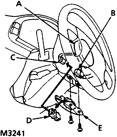
- Driver's airbag
- Cable reel 3 – P connector
- Driver's airbag 3 – P connector
- Short connector – RED
- Access panel
- Remove access panel from steering wheel, then remove short connector – RED from panel.
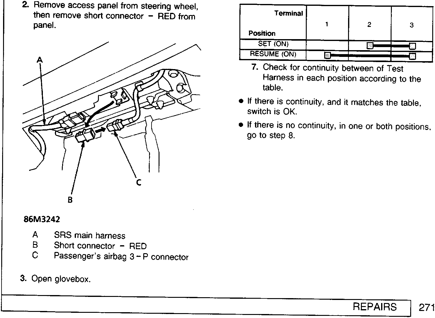
- SRS main harness
- Short connector – RED
- Passenger's airbag 3 – P connector
- Open glovebox.
- Disconnect 3 – P connector between passenger's airbag and SRS harness, then connect Test Harness to the cable reel 6 – P connector.
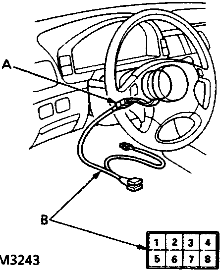
- Cable reel 6 – P connector
- Test harness
- Remove dashboard lower cover.
- Disconnect 6 – P connector between cable reel and SRS main harness, then connect Test Harness to cable reel 6 – P connector.
| Terminal | 1 | 2 | 3 |
|---|---|---|---|
| Position | |||
| SET (ON) | ■ | ■ | |
| RESUME (ON) | ■ | ■ |
- Check for continuity between of Test Harness in each position according to the table.
- If there is continuity, and it matches the table, switch is OK.
- If there is no continuity, in one or both positions, go to step 8.
Parts & tools for this job For Rover 600
- TOOLDigital multimeterSearch: automotive digital multimeter
- PARTAssorted fuse kitSearch: car fuse assortment kit
- TOOLWire crimper and connector kitSearch: wire crimper connector kit
Links open Amazon search results in a new tab. As an Amazon Associate I earn from qualifying purchases.