
Terminals
- Make
- Rover
- Model
- 600 Rover 600 Repair Manual - Volumes 1 and 2 - 2nd Edition
- Section
- Repairs › Terminals
ElectricalTerminals
Terminals
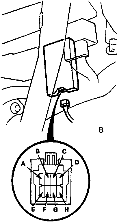
86M 2080
- A Radiator fan control module
- B 8 – P connector
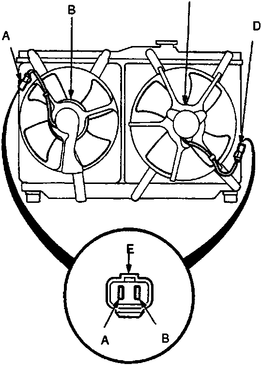
86M 2081
- A 2 – P connector
- B Condenser fan motor
- C Radiator fan motor
- D 2 – P connector
| Terminal | Wire | Connects to |
|---|---|---|
| A | YEL/WHT | Condenser fan relay – |
| YEL/BLK | Power supply and radiator fan relay + with ignition ON | |
| C | – | Not used |
| D | BLK | Earth (G401) |
| E | WHT/GRN | Engine coolant temperature (ECT) switch B |
| F | WHT' | Constant power |
| G | BLK/YEL' | IG1 (timer reset signal) |
| H | BLU | Condenser fan relay( + ) |
Fan Motor Test
- Disconnect the 2 – P connectors from each fan motor.
- Test the motor by connecting battery power to the B terminal and earth to the A terminal.
- If the motor fails to run or does not run smoothly, replace it.
Parts & tools for this job For Rover 600
- TOOLDigital multimeterSearch: automotive digital multimeter
- PARTAssorted fuse kitSearch: car fuse assortment kit
- TOOLWire crimper and connector kitSearch: wire crimper connector kit
Links open Amazon search results in a new tab. As an Amazon Associate I earn from qualifying purchases.