
Combination light switch
- Make
- Rover
- Model
- 600 Rover 600 Repair Manual - Volumes 1 and 2 - 2nd Edition
- Section
- Repairs › Combination light switch
ElectricalCombination light switch · page 1 of 2
(Internal connection)
(Internal connection)
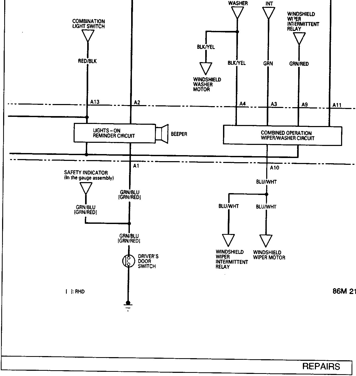
COMBINATION LIGHT SWITCH
RED/BLK
A13
A2
LIGHTS – ON REMINDER CIRCUIT
BEEPER
Safety Indicator (in the gauge assembly)
GRN/BLU [GRN/RED]
GRN/BLU [GRN/RED]
DRIVER'S DOOR SWITCH
[ ]: RHD
WINDSHIELD WIPER/WASHER SWITCH
WASHER
INT
WINDSHIELD WIPER INTERMITTENT RELAY
BLK/YEL
BLK/YEL
GRN
GRN/RED
A4
A3
A9
A11
COMBINED OPERATION WIPER/WASHER CIRCUIT
A10
BLU/WHT
BLU/WHT
WINDSHIELD WIPER INTERMITTENT RELAY
WINDSHIELD WIPER MOTOR
Parts & tools for this job For Rover 600
- TOOLOBD2 scannerSearch: OBD2 scanner
- TOOLDigital multimeterSearch: automotive digital multimeter
- TOOLBack-probe test leadsSearch: back probe test leads
Links open Amazon search results in a new tab. As an Amazon Associate I earn from qualifying purchases.