
Motor Test
- Make
- Rover
- Model
- 600 Rover 600 Repair Manual - Volumes 1 and 2 - 2nd Edition
- Section
- Repairs › Motor Test
ElectricalMotor Test
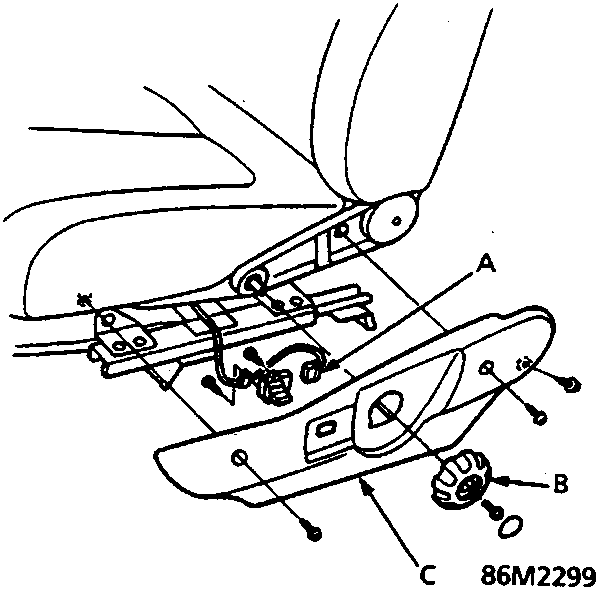
- A 5 – P Connector
- B Dial
- C Adjuster cover
- Remove the dial, and then remove the adjuster cover from the driver's seat by removing the three screws.
- Disconnect the 5 – P connector from the power seat switch, then remove the power seat switch from the adjuster cover by removing its two mounting screws.
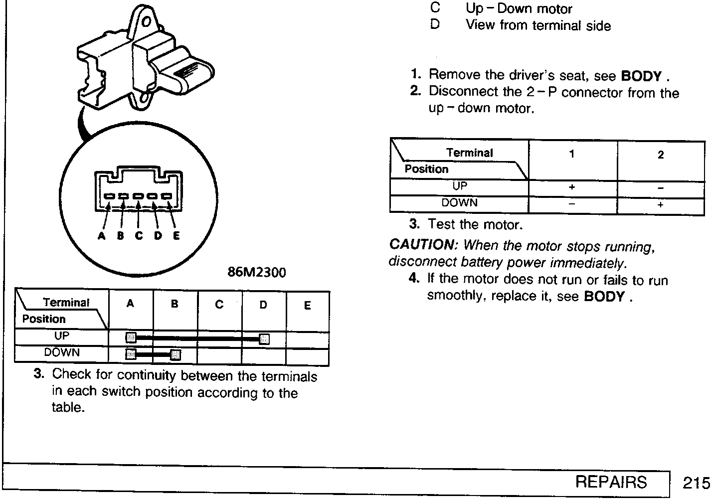
| Terminal | A | B | C | D | E |
|---|---|---|---|---|---|
| Position | |||||
| UP | ■ | ■ | ■ | ■ | ■ |
| DOWN | ■ | ■ | ■ |
- Check for continuity between the terminals in each switch position according to the table.
Motor Test
CAUTION: Be careful not to damage the seat, interior trim or body.
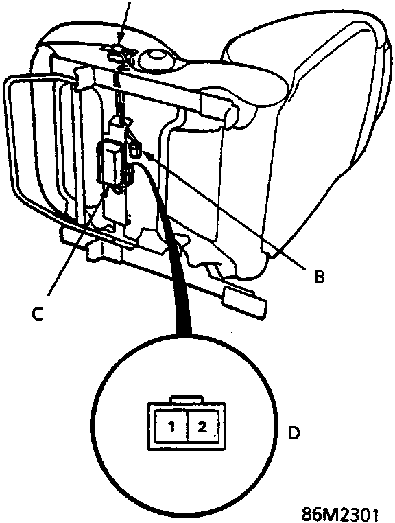
- A Power seat switch
- B 2 – P connector
- C Up – Down motor
- D View from terminal side
- Remove the driver's seat, see BODY.
- Disconnect the 2 – P connector from the up – down motor.
| Terminal | 1 | 2 |
|---|---|---|
| Position | ||
| UP | + | – |
| DOWN | – | + |
- Test the motor.
CAUTION: When the motor stops running, disconnect battery power immediately.
- If the motor does not run or fails to run smoothly, replace it, see BODY.
Parts & tools for this job For Rover 600
- TOOLDigital multimeterSearch: automotive digital multimeter
- PARTAssorted fuse kitSearch: car fuse assortment kit
- TOOLWire crimper and connector kitSearch: wire crimper connector kit
Links open Amazon search results in a new tab. As an Amazon Associate I earn from qualifying purchases.