
Recommended Procedure:
- Make
- Rover
- Model
- 600 Rover 600 Repair Manual - Volumes 1 and 2 - 2nd Edition
- Section
- Repairs › Recommended Procedure:
ElectricalRecommended Procedure:
Note: The air temperature must be between 15°C and 38°C (59°F and 100°F) before testing.
Recommended Procedure:
- Use a starter system tester.
- Connect and operate the equipment in accordance with manufacturer's instructions.
- Test and fault find as described.
Alternative Procedure:
- Use the following equipment:
– Ammeter, 0 ÷ 400 A
– Voltmeter, 0 ÷ 20 V (accurate within 0.1 volt)
– Tachometer, 0 ÷ 1200 rpm
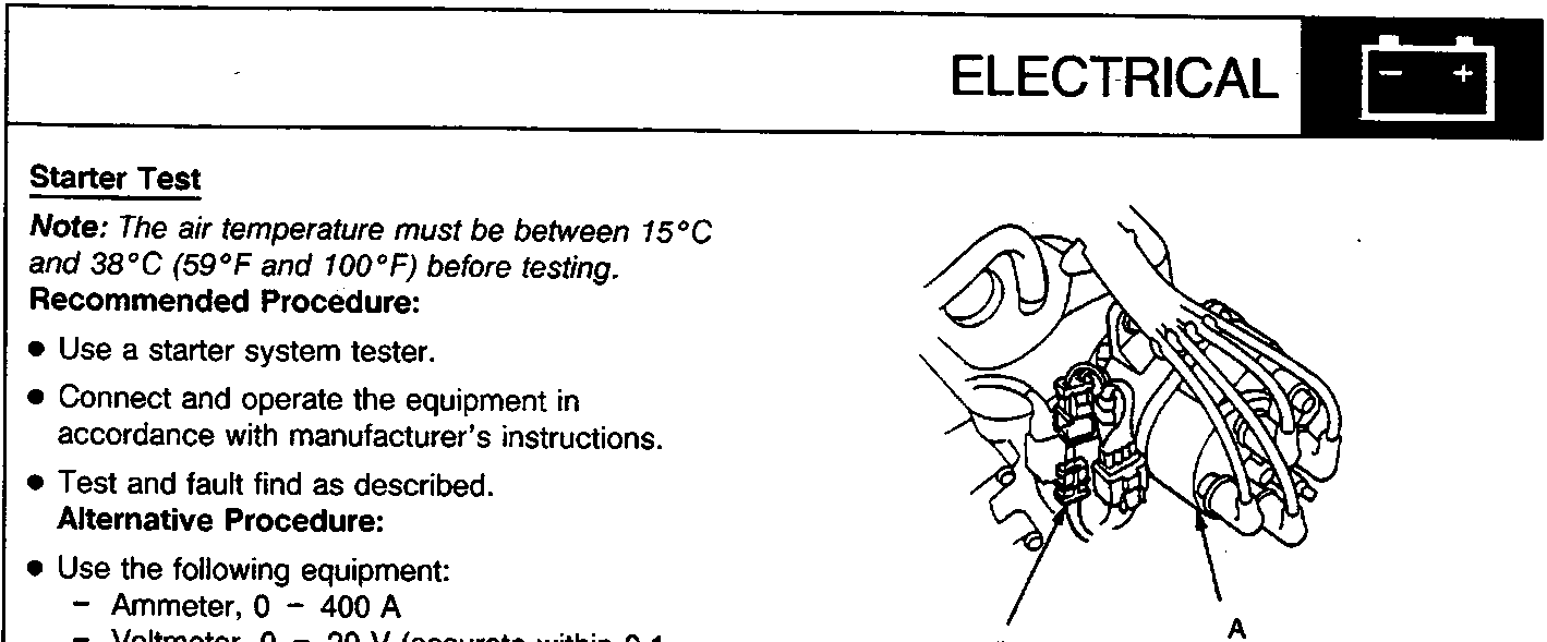
A Distributor
B 2 – P connector
- Remove the 2 – P connector from its bracket and disconnect it.
- Check the starter engagement: Turn the ignition switch to III (START). The starter should crank the engine.
- If the starter does not crank the engine, check the battery, battery positive cable, earth and the wire connections for looseness and corrosion, and test again.
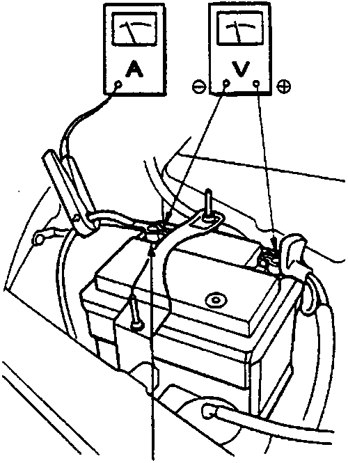
A Negative terminal
● Connect the voltmeter and ammeter as shown.
Note: After this test, or any subsequent repair, reset the engine control module (ECM) to clear any codes.
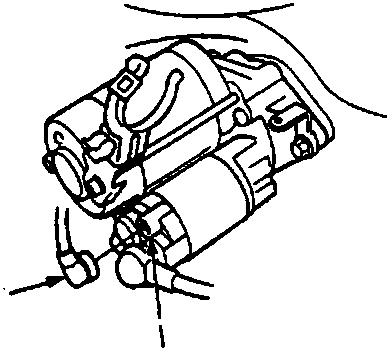
A Solenoid terminal
B BLK/WHT wire
● If the starter still does not crank the engine, bypass the ignition switch circuit as follows: Unplug the BLK/WHT wire from the solenoid terminal. Connect a jumper wire from the battery positive (+) terminal to the solenoid terminal. The starter should crank the engine.
Parts & tools for this job For Rover 600
- TOOLDigital multimeterSearch: automotive digital multimeter
- PARTAssorted fuse kitSearch: car fuse assortment kit
- TOOLWire crimper and connector kitSearch: wire crimper connector kit
Links open Amazon search results in a new tab. As an Amazon Associate I earn from qualifying purchases.