
Front Passenger Door:
- Make
- Rover
- Model
- 600 Rover 600 Repair Manual - Volumes 1 and 2 - 2nd Edition
- Section
- Repairs › Front Passenger Door:
ElectricalFront Passenger Door:
- Remove the passenger door panel, see BODY.
Front Passenger Door:
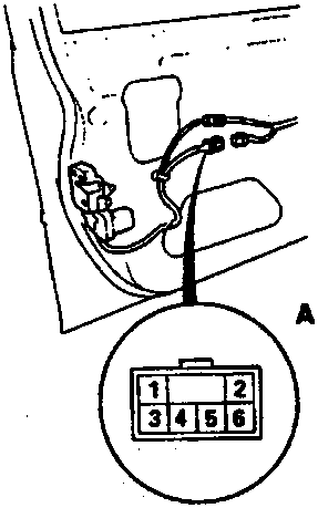
A View from wire side
- Disconnect the 6 – P connector from the door lock actuator.
- Test the actuator.
Note:
- The illustration shows the front passenger door of the LHD type, RHD type is symmetrical.
Rear Passengers Door:
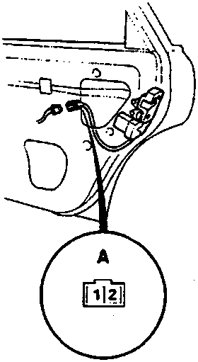
A View from wire side
- Disconnect the 2 – P connector from the door lock actuator.
- Test the actuator.
| Terminal Position | 3 (1 rear) | 4 (2 rear) |
|---|---|---|
| LOCK | – | + |
| UNLOCK | + | – |
CAUTION: To prevent damage to the actuator, connect battery power only momentarily.
- Check for continuity between the terminals in lock and unlock position according to the table.
- If the actuator does not work properly, replace it.
Original page
Parts & tools for this job For Rover 600
- TOOLTrim removal tool kitSearch: trim removal tool kit
- PARTTouch-up paintSearch: Rover touch up paint
- PARTPanel clip assortmentSearch: Rover panel clips assortment
Links open Amazon search results in a new tab. As an Amazon Associate I earn from qualifying purchases.