
Description
- Make
- Rover
- Model
- 600 Rover 600 Repair Manual - Volumes 1 and 2 - 2nd Edition
- Section
- Repairs › Description
ElectricalDescription · page 1 of 3
Description
For the stereo radio/cassette player description, please see the owner’s manual.
The power antenna mast is controlled by the radio ON/OFF switch. It will extend fully whenever the radio switch and the ignition switch a re on at the same time. When the radio or the ignition is shut off, the antenna retracts fully. The antenna motor has a built – in relay together with a limit switch for this function.
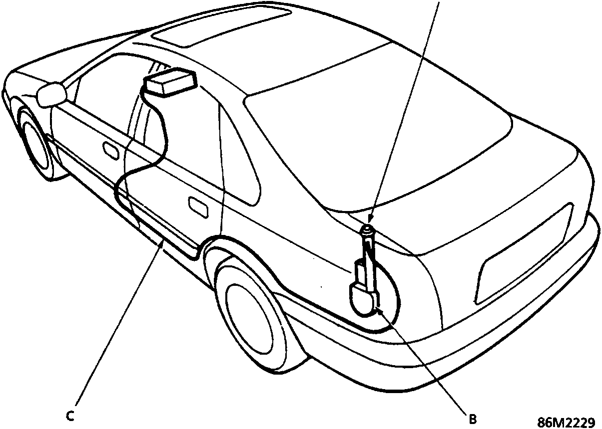
- A Antenna mast
- B Power antenna motor
- C Antenna lead
Parts & tools for this job For Rover 600
- TOOLDigital multimeterSearch: automotive digital multimeter
- PARTAssorted fuse kitSearch: car fuse assortment kit
- TOOLWire crimper and connector kitSearch: wire crimper connector kit
Links open Amazon search results in a new tab. As an Amazon Associate I earn from qualifying purchases.