
Indicator Input Test
- Make
- Rover
- Model
- 600 Rover 600 Repair Manual - Volumes 1 and 2 - 2nd Edition
- Section
- Repairs › Indicator Input Test
ElectricalIndicator Input Test · page 1 of 2
Indicator Input Test
CAUTION:
- All SRS electrical wiring harnesses are covered with yellow outer insulation.
- Replace the entire affected SRS harness assembly if it has an open circuit or damaged wiring.
- Before disconnecting the SRS wiring harness, turn the ignition switch off, disconnect the negative and positive battery cables, and wait at least three minutes.
- Remove the gauge assembly and disconnect all connectors from it.
- Inspect the connector and socket terminals to be sure they are making good contact.
- If the terminals are bent, loose or corroded, repair them as necessary, and recheck the system.
- If the terminals look OK, make the following input tests at the 30 – P connector.
- – If a test indicates a problem, find and correct the cause, then recheck the system.
- – If all the input test prove OK, but the indicator is faulty, replace the main printed circuit board.
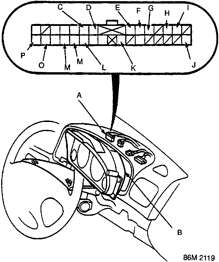
- A 30 – P connector
- B Gauge assembly
Parts & tools for this job For Rover 600
- TOOLDigital multimeterSearch: automotive digital multimeter
- PARTAssorted fuse kitSearch: car fuse assortment kit
- TOOLWire crimper and connector kitSearch: wire crimper connector kit
Links open Amazon search results in a new tab. As an Amazon Associate I earn from qualifying purchases.