
Ignition Control Module (ICM) Input Test
- Make
- Rover
- Model
- 600 Rover 600 Repair Manual - Volumes 1 and 2 - 2nd Edition
- Section
- Repairs › Ignition Control Module (ICM) Input Test
ElectricalIgnition Control Module (ICM) Input Test
- Connect a tachometer to the test tachometer connector.
Idle speed: 770 ± 50 rpm with gear lever in neutral position and electrical systems turned off.
- Adjust the idle speed if necessary.
Ignition Control Module (ICM) Input Test
Note:
- Perform an input test for the ignition control module (ICM) after finishing the fundamental tests for the ignition system and the fuel and emissions system.
- The tachometer should operate normally.
- Remove the distributor cap, the distributor rotor, and the inner cover.
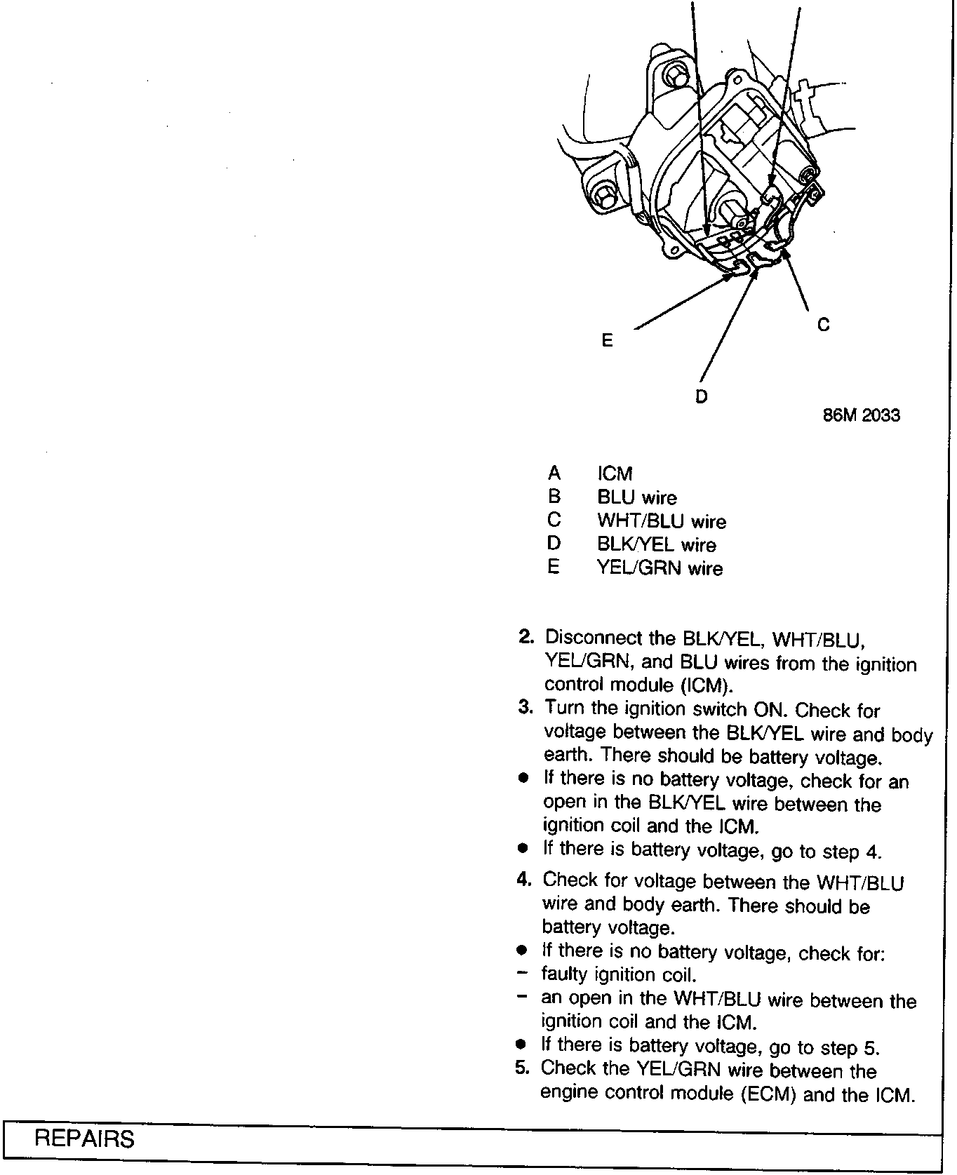
- A ICM
- B BLU wire
- C WHT/BLU wire
- D BLK/YEL wire
- E YEL/GRN wire
- Disconnect the BLK/YEL, WHT/BLU, YEL/GRN, and BLU wires from the ignition control module (ICM).
- Turn the ignition switch ON. Check for voltage between the BLK/YEL wire and body earth. There should be battery voltage.
- If there is no battery voltage, check for an open in the BLK/YEL wire between the ignition coil and the ICM.
- If there is battery voltage, go to step 4.
- Check for voltage between the WHT/BLU wire and body earth. There should be battery voltage.
- If there is no battery voltage, check for:
- faulty ignition coil.
- an open in the WHT/BLU wire between the ignition coil and the ICM.
- If there is battery voltage, go to step 5.
- If there is no battery voltage, check for:
- Check the YEL/GRN wire between the engine control module (ECM) and the ICM.
Parts & tools for this job For Rover 600
- TOOLOBD2 scannerSearch: OBD2 scanner
- TOOLDigital multimeterSearch: automotive digital multimeter
- TOOLBack-probe test leadsSearch: back probe test leads
Links open Amazon search results in a new tab. As an Amazon Associate I earn from qualifying purchases.