
Ignition control module (icm)
- Make
- Rover
- Model
- 600 Rover 600 Repair Manual - Volumes 1 and 2 - 2nd Edition
- Section
- Repairs › Ignition control module (icm)
ElectricalIgnition control module (icm)
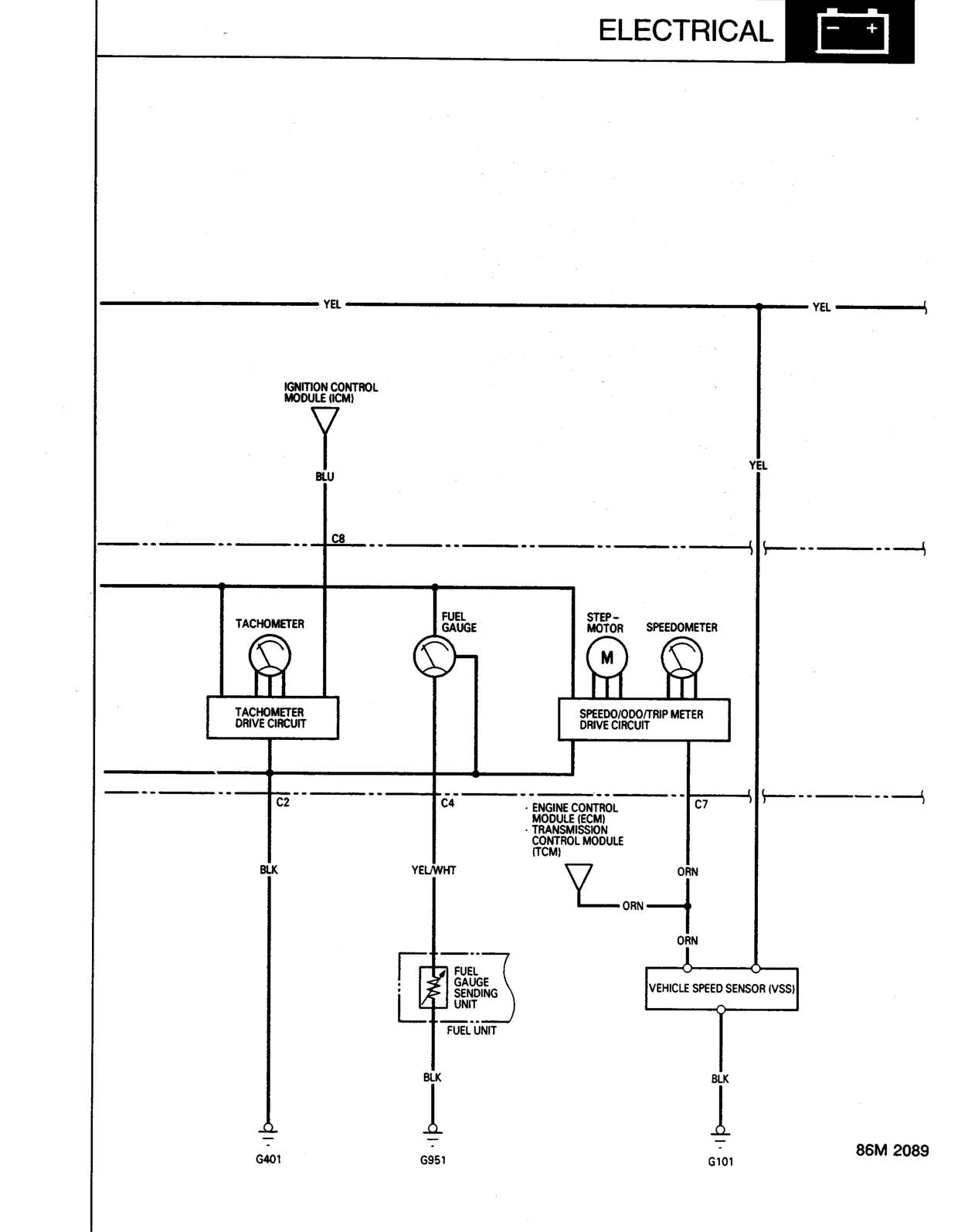
IGNITION CONTROL MODULE (ICM)
TACHOMETER
FUEL GAUGE
SPEEDO/ODO/TRIP METER DRIVE CIRCUIT
ENGINE CONTROL MODULE (ECM)
TRANSMISSION CONTROL MODULE (TCM)
VEHICLE SPEED SENSOR (VSS)
C8
C2
C4
C7
BLU
YEL
YEL/WHT
ORN
BLK
G401
G951
G101
Original page
Parts & tools for this job For Rover 600
- TOOLOBD2 scannerSearch: OBD2 scanner
- TOOLDigital multimeterSearch: automotive digital multimeter
- TOOLBack-probe test leadsSearch: back probe test leads
Links open Amazon search results in a new tab. As an Amazon Associate I earn from qualifying purchases.