
Rotor Slip Ring Test
- Make
- Rover
- Model
- 600 Rover 600 Repair Manual - Volumes 1 and 2 - 2nd Edition
- Section
- Repairs › Rotor Slip Ring Test
ElectricalRotor Slip Ring Test
Rotor Slip Ring Test
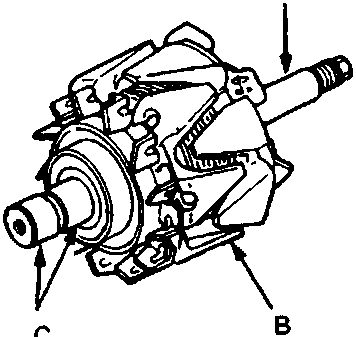
86M 2060
| A | rotor shaft |
| B | Rotor |
| C | Slip rings |
- Check for continuity between the slip rings. There should be continuity.
- Check for continuity between the slip rings and the rotor or rotor shaft. There should be no continuity.
- If the rotor fails either continuity check, replace the rotor.
Stator Test
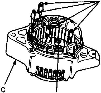
86M 2070
| A | Leads |
| B | Coil core |
| C | Stator |
- Check for continuity between each pair of leads. There should be continuity.
- Check for continuity between each lead and the coil core. There should be no continuity.
- If the coil fails either continuity check, replace the stator.
Parts & tools for this job For Rover 600
- PARTBrake padsSearch: Rover 600 brake pads
- TOOLCaliper piston rewind toolSearch: brake caliper piston rewind tool
- FLUIDBrake fluidSearch: brake fluid
Links open Amazon search results in a new tab. As an Amazon Associate I earn from qualifying purchases.