
Electrical (page 7 of 7)
- Make
- Rover
- Model
- 600 Rover 600 Repair Manual - Volumes 1 and 2 - 2nd Edition
- Section
- Repairs
ElectricalElectrical · page 7 of 7
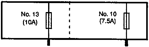
AUXILIARY FUSE HOLDER
| No. 13 (10A) |
No. 10 (7.5A) |
|---|---|
| [Fuse symbol] | [Fuse symbol] |
UNDER-DASH FUSE/RELAY BOX
- GAUGE LIGHTS
- A/T GEAR POSITION CONSOLE LIGHT
- A/T GEAR POSITION INDICATOR DIMMING CIRCUIT
- REAR FOG LIGHT SWITCH LIGHT
- HAZARD WARNING SWITCH LIGHT
- REAR WINDOW DEMISTER SWITCH LIGHT
- HEATER CONTROL PANEL LIGHT
- MASTER POWER WINDOW SWITCH LIGHT
- DASH LIGHTS BRIGHTNESS CONTROLLER
- CIGARETTE LIGHTER
- CLOCK
- STEREO RADIO/CASSETTE PLAYER
- INTEGRATED CONTROL UNIT
- LEFT FRONT PARKING LIGHT (5W)
- RIGHT FRONT PARKING LIGHT (5W)
- LEFT TAILLIGHT (5W)
- RIGHT TAILLIGHT (5W)
- LICENCE PLATE LIGHTS (5W x 2)
- GLOVE BOX LID OPEN / GLOVE BOX LIGHT (5W)
Parts & tools for this job For Rover 600
- TOOLDigital multimeterSearch: automotive digital multimeter
- PARTAssorted fuse kitSearch: car fuse assortment kit
- TOOLWire crimper and connector kitSearch: wire crimper connector kit
Links open Amazon search results in a new tab. As an Amazon Associate I earn from qualifying purchases.