
Workshop Manuals Factory service & repair Rover
01 Information02 General data03 Engine04 Engine management system – PGM-Fi05 Cooling system, manifold and exhaust06 Clutch07 Manual gearbox08 Automatic gearbox09 Drive shafts10 Differential – manual gearbox11 Differential – automatic gearbox12 Steering13 Suspension14 Brakes and ABS15 Brakes – ABS BY416 Body17 Heating and ventilation18 Electrical19 Supplementary restraint system (SRS)
Rover Rover 600 Repair Manual - Volumes 1 and 2 - 2nd Edition18 · Electrical
18 · Electrical

Electrical (page 5 of 7)

Make
Rover
Model
600 Rover 600 Repair Manual - Volumes 1 and 2 - 2nd Edition
Section
Repairs
ElectricalElectrical · page 5 of 7

Electrical (page 5 of 7) – diagram from the Electrical chapter of the Rover Rover 600 Repair Manual - Volumes 1 and 2 - 2nd Edition factory manual.
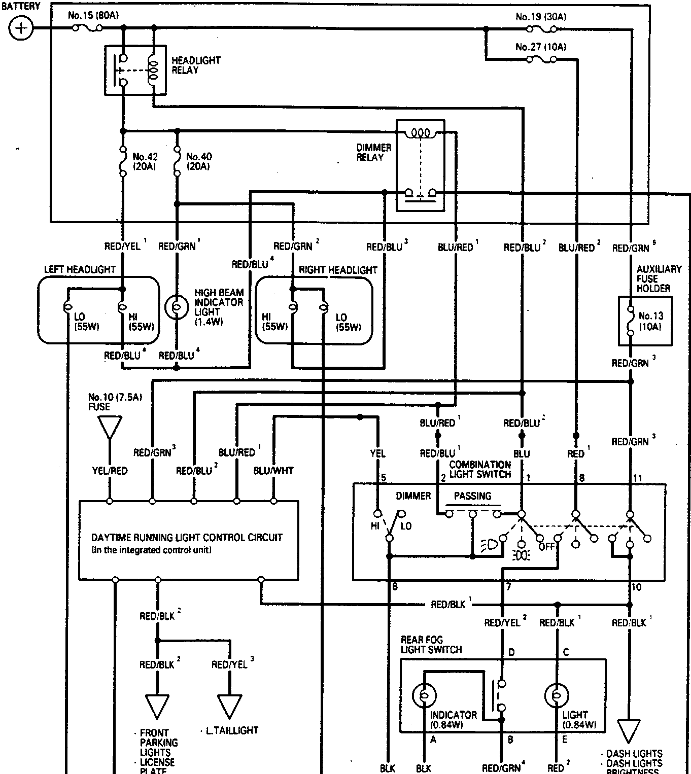
Electrical circuit diagram showing connections for headlights, fuses, relays, switches, and ground points. Includes labels such as BATTERY, UNDER-HOOD FUSE/RELAY BOX, LEFT HEADLIGHT, RIGHT HEADLIGHT, DIMMER RELAY, COMBINATION LIGHT SWITCH, DAYTIME RUNNING LIGHT CONTROL CIRCUIT, REAR FOG LIGHT SWITCH, and various wire color codes and ground points G301, G203, G201, G401, G501. Document code 86M 2139 is printed at bottom right.

Parts & tools for this job For Rover 600

Links open Amazon search results in a new tab. As an Amazon Associate I earn from qualifying purchases.