
86M 2042 (page 2 of 3)
- Make
- Rover
- Model
- 600 Rover 600 Repair Manual - Volumes 1 and 2 - 2nd Edition
- Section
- Repairs
Electrical86M 2042 · page 2 of 3
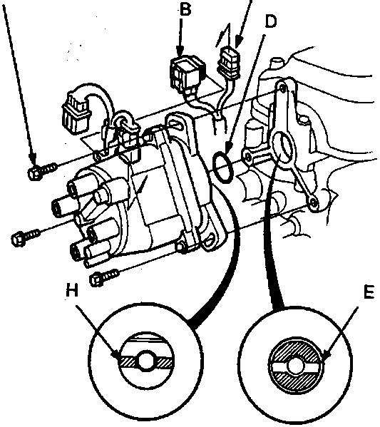
86M 2046
- A Mounting bolts
- B 8-P connector
- C 2-P connector
- D New O-ring
- E Grooves
- F Camshaft end
- G Distributor end
- H Lugs
- Coat a new O-ring with engine oil, then install it.
- Slip the distributor into position.
Note: The lugs on the end of the distributor, and the mating grooves in the camshaft end are both offset to eliminate the possibility of installing the distributor 180° out of time.
- Install the mounting bolts and tighten them temporarily.
- Connect the 2-P and 8-P connectors to the distributor.
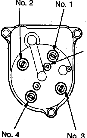
86M 2047
- A No. 1 cylinder mark
- Connect the ignition wires as shown.
- Set the timing with a timing light.
- After setting the timing, tighten the mounting bolts.
Note: Before you install the distributor, bring the No. 1 piston to compression stroke TDC.
Parts & tools for this job For Rover 600
- TOOLDigital multimeterSearch: automotive digital multimeter
- PARTAssorted fuse kitSearch: car fuse assortment kit
- TOOLWire crimper and connector kitSearch: wire crimper connector kit
Links open Amazon search results in a new tab. As an Amazon Associate I earn from qualifying purchases.