
86M 2155 (page 2 of 2)
- Make
- Rover
- Model
- 600 Rover 600 Repair Manual - Volumes 1 and 2 - 2nd Edition
- Section
- Repairs
Electrical86M 2155 · page 2 of 2
- Remove the switch and disconnect the connector from it.
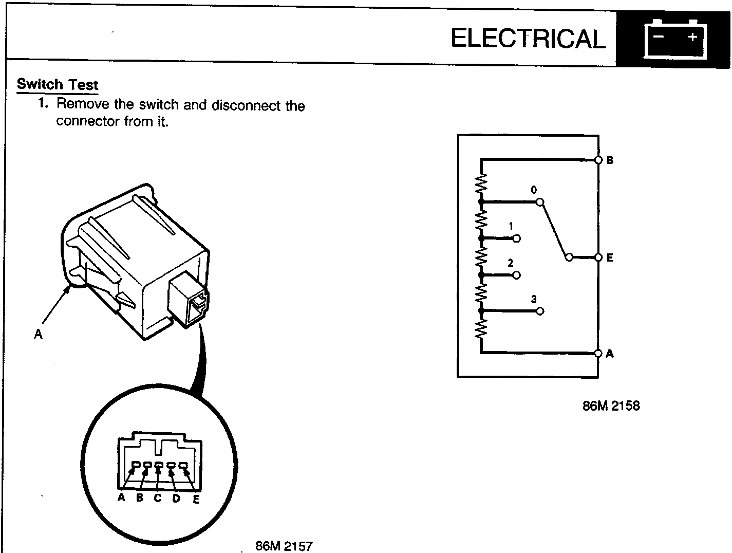
A Headlight adjuster switch
- Measure the resistance between the A and B terminals, and then measure the resistance between the B and E terminals at position 0, 1, 2 and 3 by rotating the dial.
Between A and B: Approx 996 Ohms
Between B and E:
| Dial position | 0 | 1 | 2 | 3 |
|---|---|---|---|---|
| Resistance [Approx. (Ohms)] | 562 | 731 | 815 | 910 |
Parts & tools for this job For Rover 600
- TOOLDigital multimeterSearch: automotive digital multimeter
- PARTAssorted fuse kitSearch: car fuse assortment kit
- TOOLWire crimper and connector kitSearch: wire crimper connector kit
Links open Amazon search results in a new tab. As an Amazon Associate I earn from qualifying purchases.