
Boot Light Test/Replacement (page 2 of 3)
- Make
- Rover
- Model
- 600 Rover 600 Repair Manual - Volumes 1 and 2 - 2nd Edition
- Section
- Repairs
ElectricalBoot Light Test/Replacement · page 2 of 3
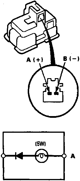
86M 2191
A From No. 29 fuse
B To boot latch switch
- Make sure that bulb is OK, then check for continuity between A (+) and B (−) terminals.
Note: This light has a diode in it. To get an accurate reading, either test it with a Volt/Ohmmeter that compensates for diode, or make sure you connect your test leads to match the polarity shown.
- If there is no continuity, replace the boot light.
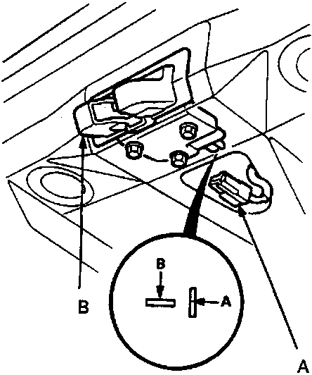
86M 2192
A 2–P connector
B Boot latch
- Open the boot lid and disconnect the 2–P connector from the boot latch.
- Check for continuity between the A and B terminals with the boot lid open.
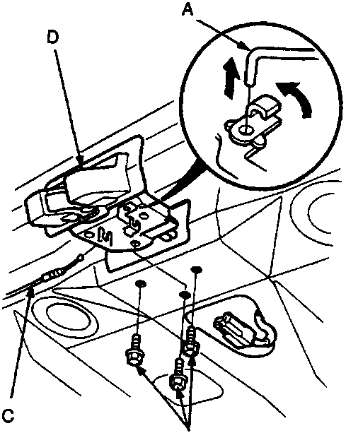
86M 2193
A Lock rod
B Bolts
C Boot opener cable
D Boot latch
Parts & tools for this job For Rover 600
- TOOLDigital multimeterSearch: automotive digital multimeter
- PARTAssorted fuse kitSearch: car fuse assortment kit
- TOOLWire crimper and connector kitSearch: wire crimper connector kit
Links open Amazon search results in a new tab. As an Amazon Associate I earn from qualifying purchases.