
Brake lights (page 2 of 2)
- Make
- Rover
- Model
- 600 Rover 600 Repair Manual - Volumes 1 and 2 - 2nd Edition
- Section
- Repairs
ElectricalBrake lights · page 2 of 2
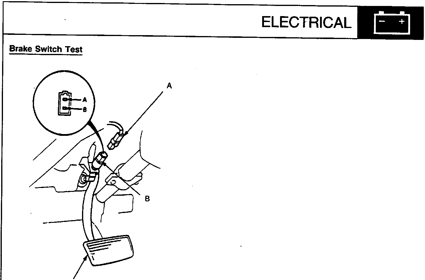
86M 2195
- A 2–P Connector
- B Brake switch
- C Brake pedal
- If the brake lights do not go on, check for:
- blown No. 41 (20 A) fuse in the engine compartment fuse/relay box.
- blown brake light bulbs in the outer tail light assembly.
- If the fuse and bulbs are OK, disconnect the 2–P connector from the brake switch.
| Terminal Position |
A | B |
|---|---|---|
| Brake pedal (Release) | ||
| Brake pedal (Push) | ██████████ |
- Check for continuity between the A and B terminals in each switch position according to the table.
- If there is no continuity with the brake pedal pushed, replace the brake switch or adjust the brake pedal height (see section 19).
- If there is continuity, but the brake lights do not go on, check for:
- faulty bulb holder panel.
- poor earth (LHD: G452, G501 RHD: G451, G701).
- an open in the WHT/YEL or GRN/WHT wire.
Parts & tools for this job For Rover 600
- PARTBrake padsSearch: Rover 600 brake pads
- TOOLBrake bleeder kitSearch: one man brake bleeder kit
- FLUIDBrake fluidSearch: brake fluid
Links open Amazon search results in a new tab. As an Amazon Associate I earn from qualifying purchases.