
Combination Light Switch Test (page 2 of 2)
- Make
- Rover
- Model
- 600 Rover 600 Repair Manual - Volumes 1 and 2 - 2nd Edition
- Section
- Repairs
ElectricalCombination Light Switch Test · page 2 of 2
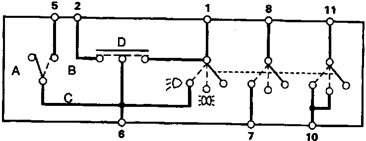
86M 2143
- A Low
- B High
- C Dip
- D Passing
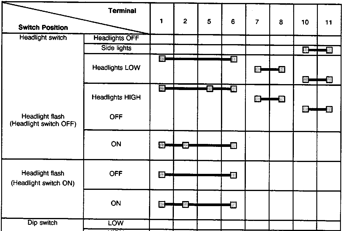
| Switch Position | Terminal | ||||||||
|---|---|---|---|---|---|---|---|---|---|
| 1 | 2 | 5 | 6 | 7 | 8 | 10 | 11 | ||
| Headlight switch | Headlights OFF | ||||||||
| Side lights | ●—● | ●—● | |||||||
| Headlights LOW | ●—● | ●—● | ●—● | ●—● | ●—● | ||||
| Headlights HIGH | ●—● | ●—● | ●—● | ●—● | ●—● | ●—● | |||
| OFF | ●—● | ●—● | |||||||
| ON | ●—● | ●—● | ●—● | ||||||
| Headlight flash (Headlight switch OFF) |
OFF | ●—● | ●—● | ●—● | |||||
| ON | ●—● | ●—● | ●—● | ||||||
| Dip switch | LOW | ||||||||
| HIGH | ●—● | ||||||||
Parts & tools for this job For Rover 600
- TOOLOBD2 scannerSearch: OBD2 scanner
- TOOLDigital multimeterSearch: automotive digital multimeter
- TOOLBack-probe test leadsSearch: back probe test leads
Links open Amazon search results in a new tab. As an Amazon Associate I earn from qualifying purchases.