
Component Location Index (page 2 of 4)
- Make
- Rover
- Model
- 600 Rover 600 Repair Manual - Volumes 1 and 2 - 2nd Edition
- Section
- Repairs
ElectricalComponent Location Index · page 2 of 4
This speedometer consists of a newly developed electrical vehicle speed sensor (VSS) and a speeds/odo/trip drive circuit. By means of bobbin type movements it eliminates engine noise – transmitted through the meter cable hole on the bulkhead and needle vibration caused by cable failure. Also, it made the ideal layout in the limited space available.
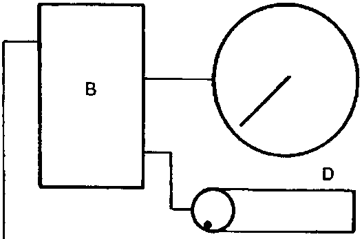
- A Speed pulse
- B Speedo/odo/trip drive circuit
- C Speedometer
- D Odo/trip meter
- E Step motor
- F Vehicle speed sensor
- G Magnet
- H Hole in IC unit
Parts & tools for this job For Rover 600
- TOOLDigital multimeterSearch: automotive digital multimeter
- PARTAssorted fuse kitSearch: car fuse assortment kit
- TOOLWire crimper and connector kitSearch: wire crimper connector kit
Links open Amazon search results in a new tab. As an Amazon Associate I earn from qualifying purchases.