
Components (page 2 of 2)
- Make
- Rover
- Model
- 600 Rover 600 Repair Manual - Volumes 1 and 2 - 2nd Edition
- Section
- Repairs
ElectricalComponents · page 2 of 2
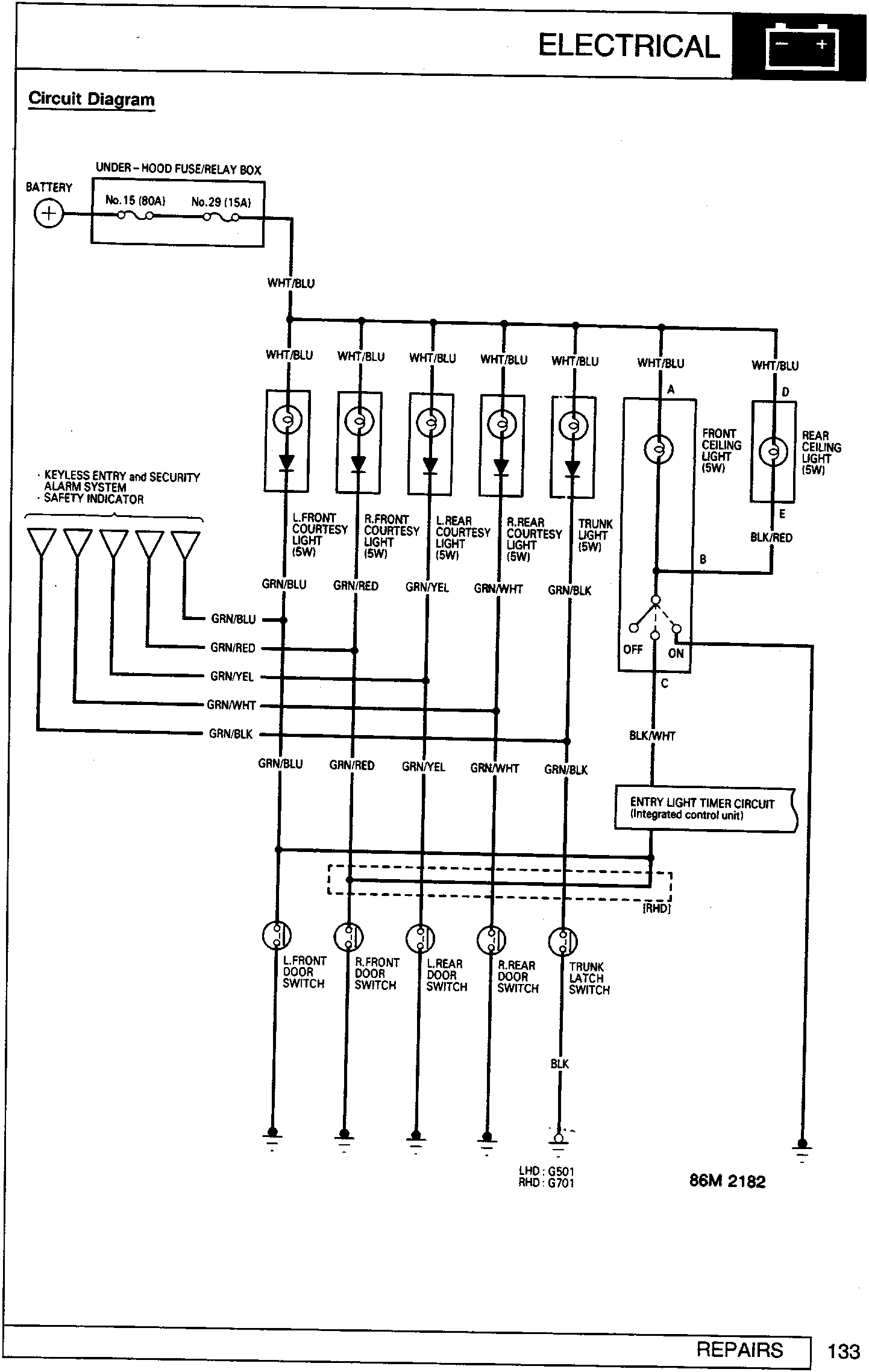
Components (page 2 of 2) – diagram from the Electrical chapter of the Rover Rover 600 Repair Manual - Volumes 1 and 2 - 2nd Edition factory manual.
Parts & tools for this job For Rover 600
- TOOLDigital multimeterSearch: automotive digital multimeter
- PARTAssorted fuse kitSearch: car fuse assortment kit
- TOOLWire crimper and connector kitSearch: wire crimper connector kit
Links open Amazon search results in a new tab. As an Amazon Associate I earn from qualifying purchases.