
Main Switch Test (page 2 of 2)
- Make
- Rover
- Model
- 600 Rover 600 Repair Manual - Volumes 1 and 2 - 2nd Edition
- Section
- Repairs
ElectricalMain Switch Test · page 2 of 2
WARNING: Observe SRS system precautions,see SRS PRECAUTIONS.
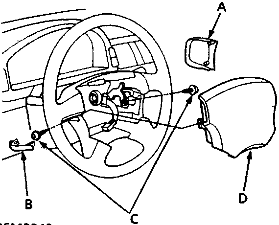
- A SET/RESUME switch cover
- B Access panel
- C TORX bolts
- D Driver’s airbag assembly
- Carefully remove access panel and SET/RESUME switch cover.
- Remove 2 TORX bolts (T30 bit), then remove the driver’s airbag assembly.
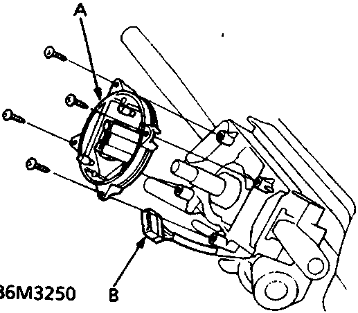
- A Slip ring
- B 5 – P connector
- Disconnect the 5 – P connector between slip ring and SRS main harness.
- Remove 4 screws and slip ring.
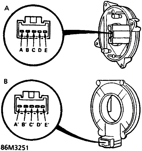
- A Front – steering wheel side
- B Rear – combination switch side
- While turning the slip ring, check for continuity between terminals:
A – A', B – B', C – C' and D – D'
There should be continuity.
- If there is no continuity at any terminal, replace slip ring.
Parts & tools for this job For Rover 600
- TOOLOBD2 scannerSearch: OBD2 scanner
- TOOLDigital multimeterSearch: automotive digital multimeter
- TOOLBack-probe test leadsSearch: back probe test leads
Links open Amazon search results in a new tab. As an Amazon Associate I earn from qualifying purchases.