
Power relays * (page 2 of 2)
- Make
- Rover
- Model
- 600 Rover 600 Repair Manual - Volumes 1 and 2 - 2nd Edition
- Section
- Repairs
ElectricalPower relays * · page 2 of 2
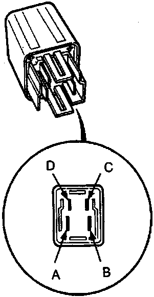
86M 2401
- Dimmer relay
- Headlight relay
- Rear window demister relay
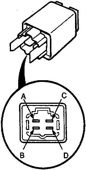
86M 2402
- Starter cut relay
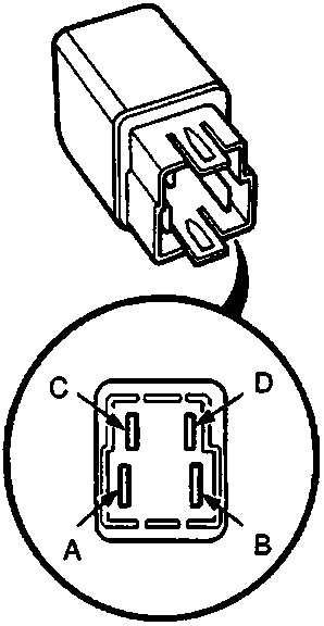
86M 1978
- ABS motor relay
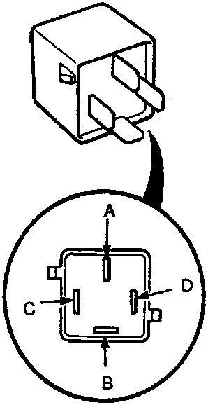
86M 1979
- ABS front fail – safe relay
- ABS rear fail – safe relay
- Blower motor relay
- Power window relay
- Radiator fan relay
- Seat heater main relay
Parts & tools for this job For Rover 600
- TOOLDigital multimeterSearch: automotive digital multimeter
- PARTAssorted fuse kitSearch: car fuse assortment kit
- TOOLWire crimper and connector kitSearch: wire crimper connector kit
Links open Amazon search results in a new tab. As an Amazon Associate I earn from qualifying purchases.