
Driver's Window Motor Test (page 2 of 3)
- Make
- Rover
- Model
- 600 Rover 600 Repair Manual - Volumes 1 and 2 - 2nd Edition
- Section
- Repairs
ElectricalDriver's Window Motor Test · page 2 of 3
Note: The control unit is built into the master power window switch.
- Lever the switch out of the rear console and disconnect the connectors.
- Inspect the connector terminals to ensure they make good contact.
- If the terminals are bent, loose or corroded, repair them as necessary, and recheck the system.
- If the terminals look OK, make the following input tests at the connectors.
- – If a test indicates a problem, find and correct the cause, then recheck the system.
- – If all input tests prove OK, the control unit must be faulty; replace the master power window switch.
Note: Different wires with the same colour have been given a number suffix to distinguish them (for example, BLK¹ and BLK² are not the same).
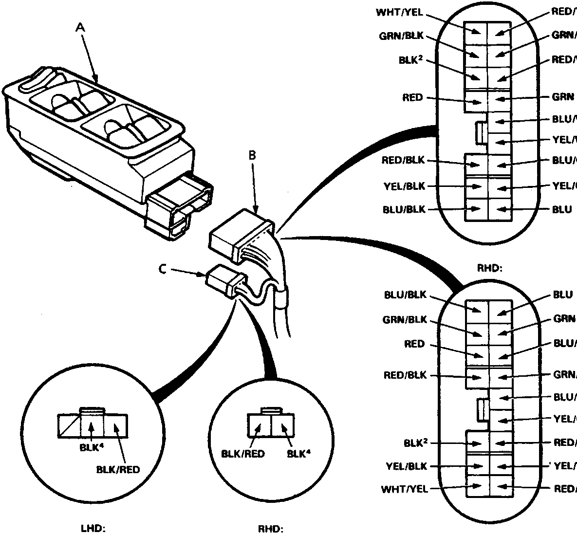
A Master power window switch
B 16 – P connector
C 3 – P (LHD) or 2 – P (RHD) connector
Parts & tools for this job For Rover 600
- TOOLTrim removal tool kitSearch: trim removal tool kit
- PARTTouch-up paintSearch: Rover touch up paint
- PARTPanel clip assortmentSearch: Rover panel clips assortment
Links open Amazon search results in a new tab. As an Amazon Associate I earn from qualifying purchases.