
Ignition Coil Test (page 2 of 3)
- Make
- Rover
- Model
- 600 Rover 600 Repair Manual - Volumes 1 and 2 - 2nd Edition
- Section
- Repairs
ElectricalIgnition Coil Test · page 2 of 3
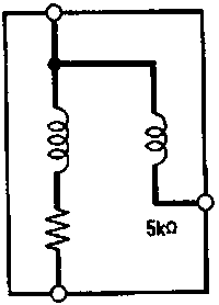
86M 2035
A Secondary winding terminal
- Using an ohmmeter, measure resistance between the terminals. If the resistance is not within specifications, replace the coil.
Note: Resistance will vary with coil temperature; specifications are at 20°C (68°F).
Primary Winding Resistance (between the A and B terminals):
0.6 – 0.8 Ohms
Secondary Winding Resistance (between the A and secondary winding terminals):
13 – 19 kOhms
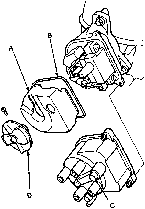
86M 2036
| A | Leak cover |
| B | Cap seal |
| C | Distributor cap |
| D | Distributor rotor |
- With the ignition switch OFF, remove the distributor cap, distributor rotor and cap seal, then remove the leak cover.
Parts & tools for this job For Rover 600
- PARTSpark plugsSearch: Rover 600 spark plugs
- TOOLSpark plug socketSearch: spark plug socket
- TOOLSpark plug gap toolSearch: spark plug gap tool
Links open Amazon search results in a new tab. As an Amazon Associate I earn from qualifying purchases.