
Starter Replacement (page 5 of 5)
- Make
- Rover
- Model
- 600 Rover 600 Repair Manual - Volumes 1 and 2 - 2nd Edition
- Section
- Repairs
ElectricalStarter Replacement · page 5 of 5
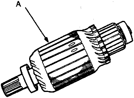
A Inspect for damage
- Inspect the armature surface for wear or damage.
- A dirty or burnt commutator surface may be resurfaced with emery cloth or a lathe within the following specifications.
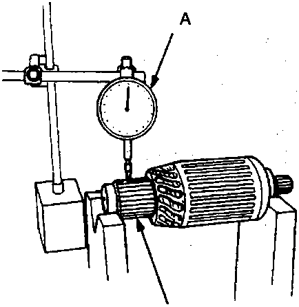
A Dial indicator
B Commutator
Commutator Runout:
Standard (New): 0 – 0.02 mm
Service Limit: 0.05 mm
- If the commutator runout and diameter are within limits, check the commutator for damage or for carbon dust or brass chips between the segments.
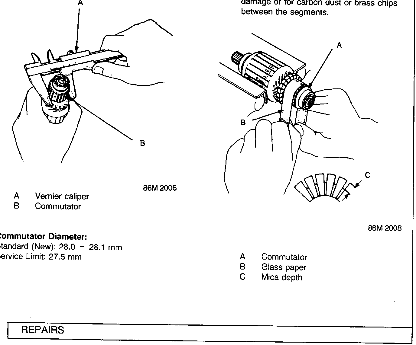
A Vernier caliper
B Commutator
Commutator Diameter:
Standard (New): 28.0 – 28.1 mm
Service Limit: 27.5 mm
A Commutator
B Glass paper
C Mica depth
Parts & tools for this job For Rover 600
- TOOLBattery testerSearch: car battery tester
- TOOLDigital multimeterSearch: automotive digital multimeter
- TOOLBattery terminal cleanerSearch: battery terminal cleaner
Links open Amazon search results in a new tab. As an Amazon Associate I earn from qualifying purchases.