
Component Location Index (page 5 of 5)
- Make
- Rover
- Model
- 600 Rover 600 Repair Manual - Volumes 1 and 2 - 2nd Edition
- Section
- Repairs
ElectricalComponent Location Index · page 5 of 5
From page 43
Turn the ignition switch off.
Check fuse No. 2 (15A) in the passenger compartment fuse/relay box.
Is the fuse OK?
- NO: Replace the fuse.
- YES
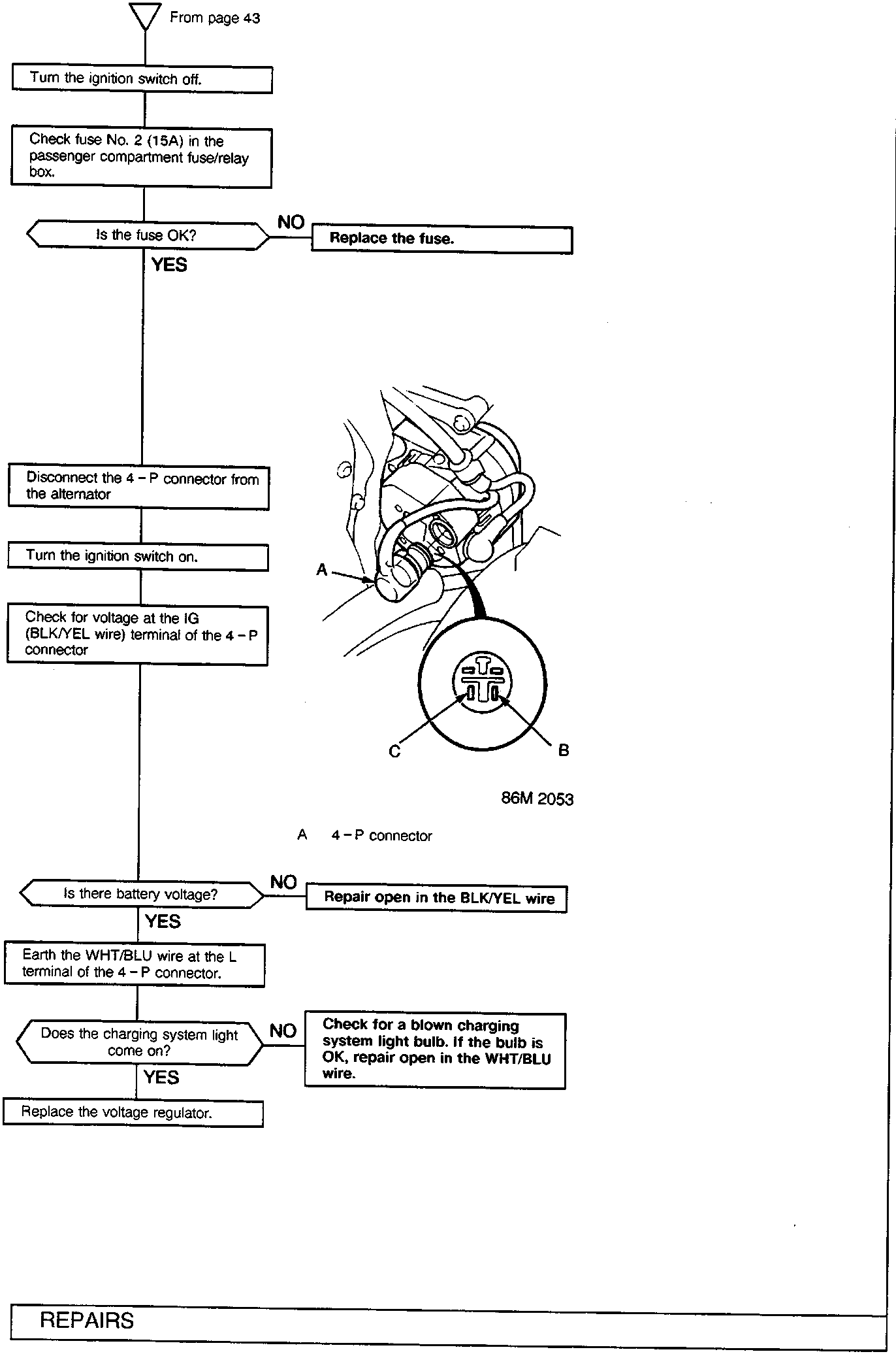
A 4-P connector
Disconnect the 4-P connector from the alternator
Turn the ignition switch on.
Check for voltage at the IG (BLK/YEL wire) terminal of the 4-P connector
Is there battery voltage?
- NO: Repair open in the BLK/YEL wire
- YES
Earth the WHT/BLU wire at the L terminal of the 4-P connector.
Does the charging system light come on?
- NO: Check for a blown charging system light bulb. If the bulb is OK, repair open in the WHT/BLU wire.
- YES
Replace the voltage regulator.
Parts & tools for this job For Rover 600
- TOOLDigital multimeterSearch: automotive digital multimeter
- PARTAssorted fuse kitSearch: car fuse assortment kit
- TOOLWire crimper and connector kitSearch: wire crimper connector kit
Links open Amazon search results in a new tab. As an Amazon Associate I earn from qualifying purchases.