
Dim-dip Headlight Control Input Test (KE) (page 3 of 5)
- Make
- Rover
- Model
- 600 Rover 600 Repair Manual - Volumes 1 and 2 - 2nd Edition
- Section
- Repairs
ElectricalDim-dip Headlight Control Input Test (KE) · page 3 of 5
CAUTION: The dim – dip resistor becomes very hot when using the dim – dip headlights. Do not touch it or the attaching hardware immediately after they have been turned off.
- Disconnect the 2 – P connector from the resistor.
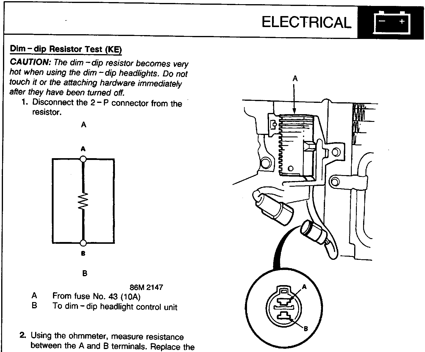
86M 2147
A From fuse No. 43 (10A)
B To dim – dip headlight control unit
- Using the ohmmeter, measure resistance between the A and B terminals. Replace the resistor if the resistance is not within specifications.
Note: Resistance will vary with the resistor temperature before and after use.
Resistance: 0.68 – 0.79 ohms
86M 2148
A Resistor (right front of engine compartment)
- If its is not within specifications, replace the dim – dip resistor.
Parts & tools for this job For Rover 600
- PARTReplacement bulbsSearch: Rover 600 bulbs
- TOOLDigital multimeterSearch: automotive digital multimeter
Links open Amazon search results in a new tab. As an Amazon Associate I earn from qualifying purchases.