
Replacement (page 4 of 5)
- Make
- Rover
- Model
- 600 Rover 600 Repair Manual - Volumes 1 and 2 - 2nd Edition
- Section
- Repairs
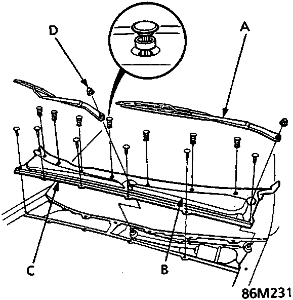
A Wiper arm
B Air scoop
C Bonnet seal
D Cap nutOpen the bonnet and remove the cap nuts and the wiper arms.
Note: Remove the wiper arms carefully without damaging the bonnet.
Remove the windshield lower molding, bonnet seal, and air scoop by prying the trim clips out and removing the screws.
Disconnect the 5 – P connector from the wiper motor, then remove the wiper harness from the wiper linkage.
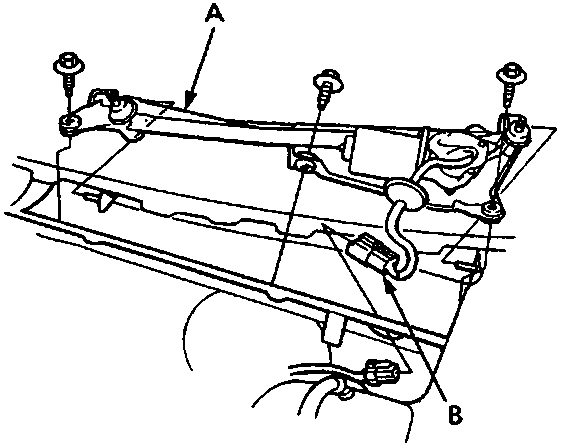
A Wiper linkage assembly
B 5 – P connectorRemove the wiper linkage assembly by removing the three mounting bolts
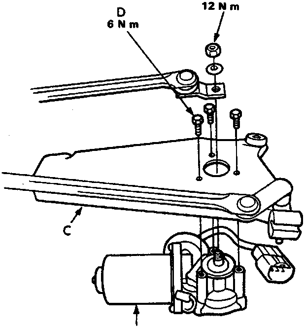
A Nut
B Wiper motor
C Wiper linkage assembly
D Mounting boltRemove the three mounting bolts and one nut from the wiper linkage to remove the wiper motor.
Install the wiper motor in the reversing order of removal.
Parts & tools for this job For Rover 600
- TOOLDigital multimeterSearch: automotive digital multimeter
- PARTAssorted fuse kitSearch: car fuse assortment kit
- TOOLWire crimper and connector kitSearch: wire crimper connector kit
Links open Amazon search results in a new tab. As an Amazon Associate I earn from qualifying purchases.